 The process of establishing electronic circuits the most exciting and interesting, but also the longest, sometimes bringing a lot of grief for Amateurs due to the lack of reliable power supply. After all, the battery or the battery do not serve indefinitely — they are discharged. Changes frequently and the line voltage. And each scheme is designed for a specific voltage. Changing it degrades the operation of the entire electronic device.
Most fully the requirements of the responsible ham radio regulated power supplies. Shown in figure 1, the scheme is simple and has the advantage that it can be conveniently used in the process of designing and establishing a simple electronic devices. The fact that this power source gives the ability to adjust the voltage applied to the schema in wide limits: from 0.5 to 15 V. This eliminates the need to buy every time you need to design the number of batteries or accumulators. This scheme another advantage is the possibility of current limiting. So, if a short circuit in the configurable circuit decreases the likelihood of breakdown of the transistors because a current overload for at least 30% of the output voltage of the power supply falls off the desktop to zero, thereby saving both the schema and the power source. The maximum current is adjustable from 3 to 100 mA, which is sufficient for most radios.
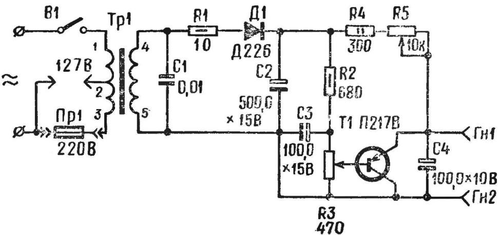
Fig. 1. Schematic diagram of regulated power supply:
the resistors R, R2 — MLT of 0.5, R4 — MLT-2; variable resistors RZ — SP, SPO 0,5 (A) R5, SP, SPO-2 (A); the capacitor C1 CTC 3; electrolytic capacitors C2—C4 — C50-6; transistor П217В is replaced by П214—П217, П4Д, П201—П203 (on heat sink).
The output voltage regulation is via transistor T1, which is enabled by the common collector circuit. In the circuit of its base potentiometer R3 forms a voltage divider. Since the output voltage depends on the voltage level, must have minimum ripple. For this purpose, and serves as a filter, consisting of capacitor C3 and resistor R2.
Variable resistor R5 controls the amount of current limit and resistor R4 limits the adjustment of resistor R5. As the voltage of the power source tends to decrease as the current increases, the voltage at the base of the transistor also decreases proportionally, This phenomenon is significantly attenuated if the capacitor C2 has a large capacity.
Power transformer Tr 1 is executed on the core Ш16Х24, the windings 1-2 and 2-3 contain 1200 turns of wire PEL-1 and 0.12, winding 4-5 — 275 turns of PEL-1 to 0.33.
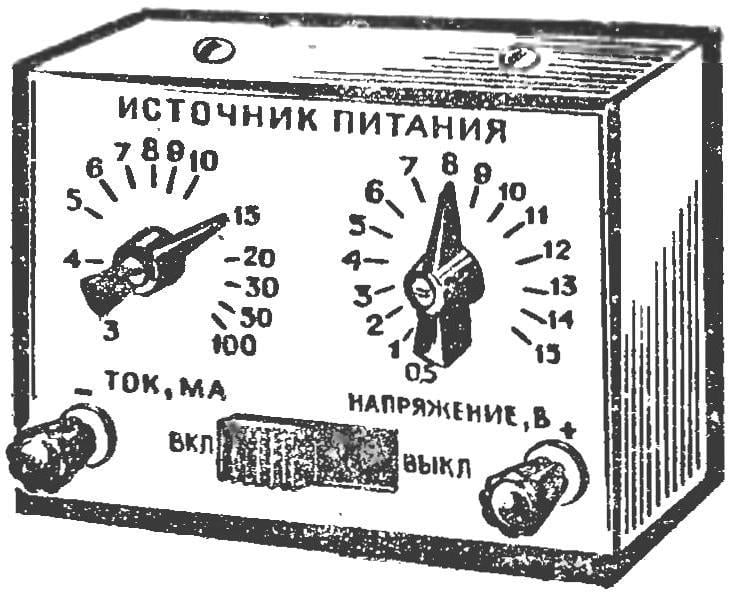
Structurally, the power supply can be made as a separate unit in a housing with dimensions 150Х110Х75 mm (Fig. 2). On front panel there are potentiometers R3 “Voltage” and R5 “Current”; socket “+” and “—”; mains switch.
After Assembly the supply unit is calibrated with a tester. The current regulator set in the middle position, and the output jacks connect the voltmeter and load resistor of 300 Ohms. Then, rotate the potentiometer RZ, on the front panel cause risks in accordance with the readings
To calibrate the current regulator, the voltage set at the level “10”; in series with the resistor R5 include the milliammeter. Then, changing the value of R5, note the front panel current values. In the process of working with the power supply regulators the voltage and current set to the appropriate division.
Of most interest to radio Amateurs represent stable sources of power. Diagram of a transistor stabilized power supply is presented in figure 3. From such a source may operate, such as a radio, both commercial and homemade, are designed for voltages from 6 to 12 V. what is the principal difference of this scheme from the above? In the diagram in figure 3, two transistors and a Zener diode D5. The transistor T1 includes not parallel to the exit, and consistently with him. The serial circuit of the regulating transistor has better efficiency, which allows to use less powerful transistors. With the help of the Zener diode D5, the value of the reference voltage is maintained constant, and this, as we have said, depends first and foremost the stability of the output voltage.
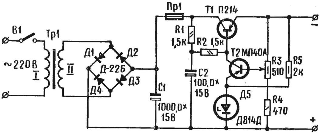
Fig. 3. Schematic diagram of the stabilized power supply:
resistors R1, R2 — MLT-0,125, R4— MLT-0,25, R5 – MLT-0,5; a variable resistor R3 — SPO-0,5; electrolytic capacitors CI, C2—C50-6; transistor П214 is replaced by П215 — Г12І7, 114Д, П201 — П203 (sink); МГ140А transistor can be replaced by MP40, МП41, МП42.
The output stabilizer voltage applied to one of the diagonals of the bridge, whose shoulders formed by the reference diode D5 and three resistors: R3, R4, R5. As the voltage on the Zener diode is kept constant, changing the magnitude of the load changes the bias current of the base of the transistor T2. For example, if the load voltage increases, the base current of the transistor T2, and with it the current of its collector will also increase That will increase the voltage drop across the resistors R1, R2 to reduce the base current of the transistor T1. The latter circumstance causes an increase in resistance of the emitter — collector of transistor T1, i.e. the increase of the voltage drop between its emitter n collector. As a result, the increase of the load voltage is largely kompensiruet.
A power source mounted on the printed circuit Board size 100X60 mm (Fig. 4). The core of the power transformer Tr 1 number of plates Ш18Х36; winding 1 contains 2550 turns of wire PEL-1 0,16; winding II — 190 turns of PEL-1 and 0.52.
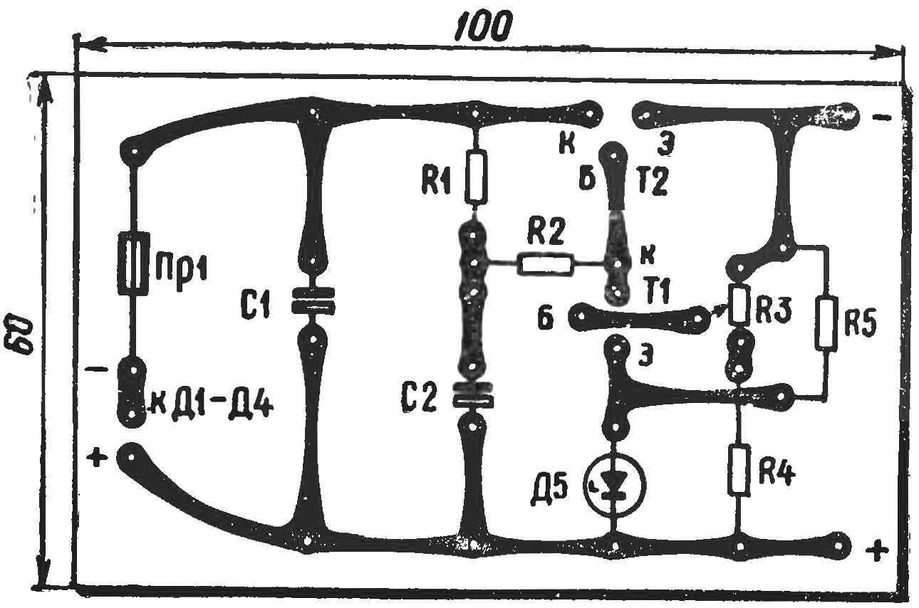
Fig. 4. PCB stable source of power.
Very often Amateurs, especially beginners, when creating a schematic no-no and will “flare”: that is, accidentally shorted the plus and minus power source. Usually fail rectifier diodes. To avoid this, the power supply, in addition to General mains fuse, install a special device protection from short circuits.
Figure 5 illustrates the diagram of a stabilized power supply with electronic protection from short circuits allows to obtain a voltage in the range from 1 to 12 and To stably support it when the current load up to 1 A.
Source adjustable stabilized voltage of the circuit is R8, R9, R10 and Zener diode D12.
The stabilized voltage from the potentiometer R10 is supplied to the input of the DC amplifier transistors T3 and T4 collected by the diagram of the composite emitter follower. By changing the position of the potentiometer changes the voltage at the base of the transistor T3, causing the voltage at the output of the circuit either increases or decreases.
The device of automatic protection from short circuits assembled on transistors T1, T2 of different conductivity. They are included in the circuit with common emitter. When opening transistor T1, the current flowing through its collector load R2, R3, causes opening of the transistor T2. In turn, the collector current of the transistor T2 is flowing through resistors R5 and R6, keeps the transistor T1 in the open.
The locking of the transistor T1 interrupts the supply of current to the base of transistor T2, whereby the latter is locked and the current in the circuit of its collector disappears.
In the closed state of the transistor T1 holds the voltage (—0,9—1,5) emitted by diodes D9—D11, the flow of current through a chain of D9, D10, D10, R1. This voltage is applied to the emitter of the transistor T1. Thus, the circuit has two stable States: closed and open.
Resistor R4 is included in series with the load circuit. When the current reaches the limit value, the voltage drop across it exceeds the locking potential on the diodes D9—D11, which leads to the unlocking of the transistors T1 and T2. Since the voltage at the collector open transistor T2 is close to zero, a DC amplifier (T3, T4) is locked and the power circuit of the load is de-energized.
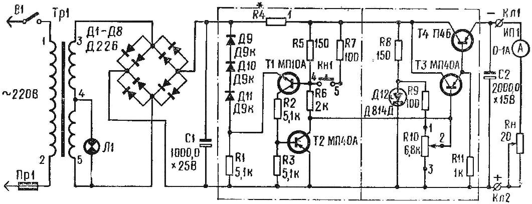
Fig. 5. Schematic diagram of power supply with electronic protection from short circuits.
After eliminating the cause of a short circuit to bring the circuit to its original state by clicking on the button KN1, included in the base circuit of the transistor T1 in series with resistor R7. Contact closure, button KN1 transistors T1 and T2 are locked, and T3, T4 are unlocked, and the voltage again supplied to the load.
The power supply applied power transformer with two windings for 6.3 V (such a transformer is used in radio receivers “Sirius-308”, “Ural-110”). Windings connected in series.
The rectifier is assembled by the bridge circuit diode Д226Б. DC voltage on the capacitor C1 must be in the range of 15 to 17 V.
The transistor T4 is mounted on heatsink size of 70X70 mm. In a radiator can be applied to any sheet metal.
The heat sink with the transistor T4, electrolytic capacitors C1, C2 and diodes D1—D8 and a power transformer Tr 1 is placed on a separate chassis, made of insulating material. Potentiometer RIO, the button KN1, the mains switch Q1, fuse holder R1 and the signal light L1 are mounted on the front panel.
Other circuit elements are mounted on a circuit Board the size of 70X50 mm, is performed by printing from folgirovannaya of Micarta (Fig. 6).
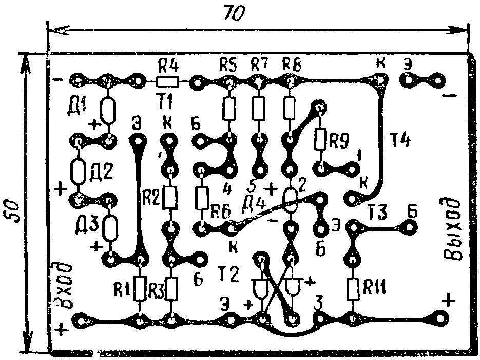
Fig. 6. PCB power supply with electronic protection.
МП10А transistor may be replaced by transistors МП11, or МП37 MP38; МП40А transistors МП13 — МП16, МП41, МП42. МП25, ЛАП26 and П4Б transistors П213 — П217.
As the diodes D9, D10, D11, in addition to Д9К, may be applied to the diodes of type D2, D7, D9, D18, D20.
Zener Д814Д, Д813, designed for a voltage of 12-13 V, can be replaced by Zener diodes with lower voltage values stabilize. Depending on the type of the used Zener diode in series with it include in the forward direction, one or two of the silicon diode type Д220, Д223, D226. For example, the Zener diode Д814Г or Д811 you need to add one diode, and the Zener diode Д814В (D810) or two. In the PCB there is a place for the installation of additional diodes. In that case, if they are needed, put a shorting bar.
All resistors are applied in circuit of the type MLT-0.5, and they can be replaced by resistors MLT-0,25 or VS-0,25. Capacitors of the type K50-3, K50-6, AGC.
In the absence of foil material can be in accordance with figure 6 in the circuit Board to drill holes for the insights details and to make a hinged mounting.
The establishment of the power source is reduced to the adjustment voltage of the Zener diode D12, which should be in the range of 12 to 13 V. Then proceed to test the regulator voltage. To the output terminals connect a load to the chain consisting of the ammeter on the 1A and resistor with a resistance of about 20 Ohms. The output voltage measured by the tester.
The PCB is fed from the output of the transistor T2. and instead of the resistor R4 set the jumper. The potentiometer R10 is moved from one extreme position to the other. The voltage should smoothly change from 0 to 12 V. Then, when a voltage of 12 V the engine move a load resistor Rh in the direction of decreasing resistance. The line current increases. At a current of 1A the voltage should not decrease more than 10%.
The establishment of the regulator ends re-soldered the output of the transistor T2 and removed the jumper.
Set the device protection from short circuits is finding the value of the resistor R4.
On the Board in one of the holes for terminals of the resistor R4, and solder a pigtail with a high specific resistance (Constantan, manganin) with a diameter of 0.2—0.3 mm, and the exposed mounting wire with a length of about 10 cm and Then by moving the end of the mounting wire on the surface of the high resistance of the conductor, making its protection circuit operation. Watching the readings of the ammeter.
Repeating the operation several times, determine exactly the value of resistor R4, when the protection is triggered reliably. Thus, one should not forget to click the “start”button.
Y. EROKHIN, V. PANOV
Recommend to read
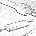 SCREW PLUS BAR…
...make a surface gauge. In the block of hard wood drilled a hole in which is screwed into the screw. Use a screwdriver to set the distance required for the application of risks. ... With a sidecar and a trailer
I read in the magazine «Modelist-Konstruktor» No. 12, 1992, A. Tatarnikov’s article «Obedient trailer». It suggested a solution to what at first glance seems a rather ordinary, but on...
