 I work as an electrician. This profession is serious, requires not only deep knowledge in this field, but also special care with electricity trifled with. I have to work in different conditions—indoors, and outdoors in any weather. Here without nice and friendly equipment assistants can not do. So I try to keep up with the technology of today, follow the latest developments in the technical literature, including in popular science. Do not bypass the attention and homemade. I learned a lot of useful information from publications in the magazines “modelist-Konstruktor”, “Radio”, etc. One of my first homemade probe, the design of which was published in the “Modeller-designer” № 5 for the year 1990.
For a long time I successfully used this probe, but one day he and I still failed: a switch was disabled, and the led glowed, showing the presence of voltage. At the time, nothing bad happened, but under other circumstances such a failure could lead to trouble. Had some time to use a test lamp (that safety rules are forbidden) or additional measuring device.
Later, in No. 4 “Modeller-designer” for the year 2001, was published a new improved version of this probe, which increases the informativeness of the previous design. In this publication I have had the idea at the base of the probe to complete the device by adding voltage meter — RV file transfer (voltmeter—V), the audio determiner phase (ZOF) and seeker of hidden wiring (ISP). In the end this idea I realized, after gathering all of the elements of the device in a single body sheath. I propose the development of readers, “Modeller-designer”.
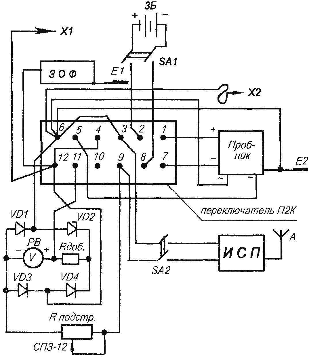
A circuit block diagram of the integrated measuring and control device of electric networks
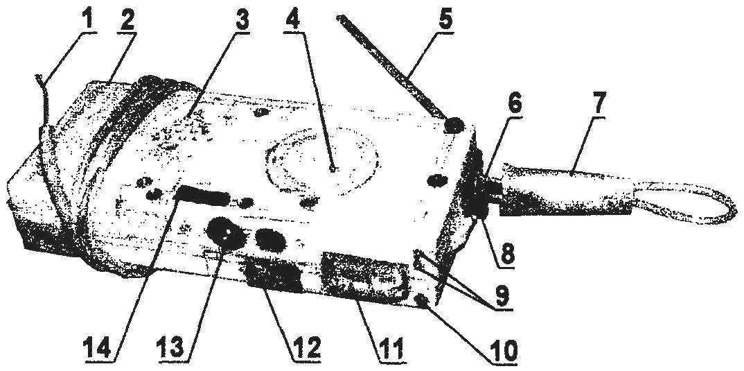
Integrated measuring and control device for electric networks:
1 — probe x2; 2— housing unit (bit set); 3 — earphone TONE-2; 4 —led COI; 5 — probe XI; 6 — a connector for the capture antenna (probe “A” ISP); 7 — trapping antenna; 8 — switch П2К; 9 — LEDs determine the polarity of the power source; 10 — led AC voltage, continuity and phase; 11 — scale of the device showing the RV; 12,13 sensors; 14 — button SA enable ISP
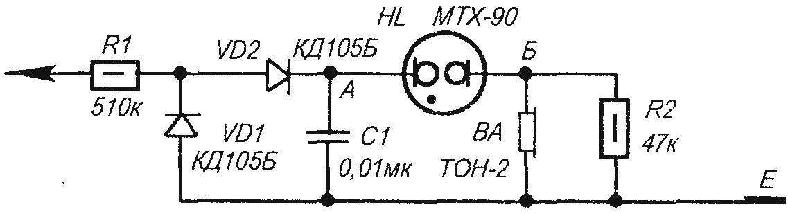
A circuit diagram of a sound identification phase ZOF
When the normally open contacts of switch П2К (see circuit block diagram) 3-2, 5-6, 8-9, 11-12 work: meter RV, ZOF, determine the phase and polarity of the power sources (LEDs НL). If continuity can and phase detection in bright Sunny weather (direct light) of the illumination of the HL probe is almost negligible (unless they are not obscure). In this case, use ZOF. Although the thyratron MTX-90 is also unlikely to be visible, but will be audible clicks headphones VA. This is the ZOF.
When the switch is pressed П2К all normally open contacts become closed and the contact 4-5 opens. In this mode, you can use the ISP button ЅА2 and test circuits showing device RV. (Do not check voltage in this mode—device RV can fail!).
Now about the individual nodes measuring integrated instrument for testing electricity.
The probe can be rented from almost any workable design, including those described in the publication “Model construction”. The main thing that it as easy as possible fit into the overall design of the device.
Sound the determinant of the phase is made on the chart provided in the magazine “Radio” No. 4 1990. Minor changes unimportant: instead of neon lamp IN-2 includes a thyratron MTX-90, buzzer TM2 is replaced by TONE 2 (you can TONE-1), the capacitance of the capacitor is reduced to 0.01 MK and a resistance R2 increased from 22 K To 47 K. When the thyratron installation should pay attention to the fact that its anode should be connected to point a And the cathode—to the point B.
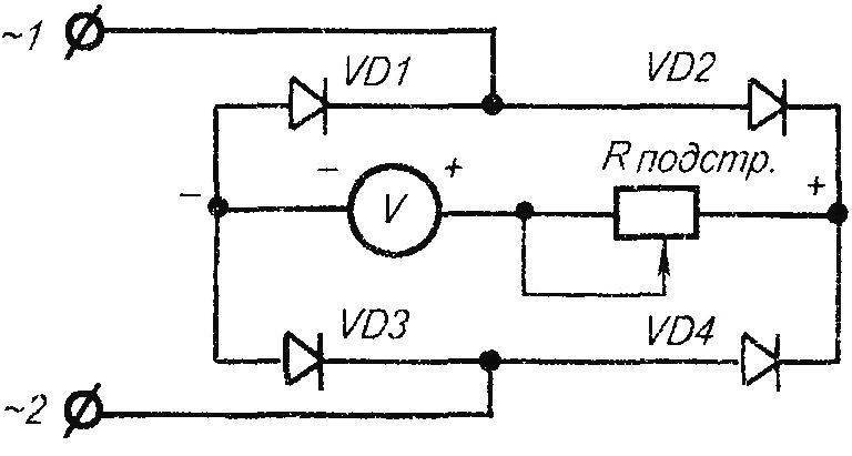
Diagram of the device showing the RV
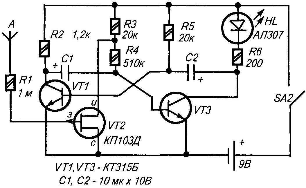
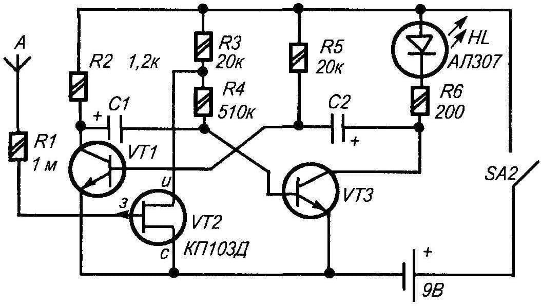
The electrical circuit finder of hidden wiring ISP
Showing the device RV is made on the basis of the voltmeter from the old tape recorder showing the recording level. This device is a DC voltage, and to display AC voltage, it should be included in the diagonal of the rectifier bridge VD1 —VD4. Diodes you can use any voltage of 300-400 V. Since the device is to be used for measuring the mains voltage 220-380 V, it should be adequately calibrate. The technology of the next calibration (Fig.Z). In the diagonal of the bridge in series with the voltmeter soldered trimmer Rпод with variable resistance 1 -2 IOM and set it at maximum resistance. Terminals 1 and 2 connected to a network 380 V. Regulator resistor is slowly moved in the direction of decreasing resistance as long as the voltmeter needle, gradually shifting to the right, not closer to the end of the scale. This position will correspond to the voltage of 380 V. Further, switching of the device from the network, measure the resulting resistance trimming of the resistor, desoldering it from the circuit and replace Rдоб constant, equal to the magnitude of the measured resistance. In my case Rдоб = 330 K. Now you can safely enable this scheme to the network 380 V and 220 V, promortional on the scale of the instrument corresponding to the cursor position. (NOTE: this work is made under high voltage with open contacts, so everything must be done gently, slowly, observing the safety rules.)
Finder flush (SP) collected under the scheme from the magazine “Radio” № 8, 1991. “A” (the intercept antenna) can be made in the form of a loop of high voltage wire, for example, from an old tube TV, or in the form of a probe with a length of 80-100 mm. the Power scheme in the author’s original version is provided from a source voltage of 9 V. However, as I have found, due to the high sensitivity of the ICP for normal operation is sufficient and 3 V.
All the constituent elements of the integrated measuring device mounted in a common casing, in which I used the box-case bit set. Case dimensions and PCB elements of the device makes no sense to cite because anyone who would do such a device, the selection of the base case will assume that he has in stock, and also of their vision of its appearance and design.
As probe X1 I used cut welding stainless steel electrode diameter of 3 mm with the Assembly in the PVC pipe. Test lead x2 soft flexible wire with a length of about 500 mm.
E1 and E2 of the sensors, the touch which begin to operate either led or thyratron 30 FA. To ensure the possibility of continuity in the process make the possibility for adjustment of RV meter in the schema introduced an adjustable resistor GPA-12 (resistance—47 K). This is necessary in order that the arrow of the device in the mode of continuity of supply, never bent or broke, hitting the side of the deflection limiter.
A. MARKIN, G. Belev
Recommend to read
 UNCLAIMED PERFECTION
Still thundering salvos of the Russo-Japanese war, an armored cruiser of Kamimura had to prove his suitability to participate in a line battle, along with the "senior comrades" — the...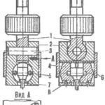 “CLOTHESPIN” FOR METAL
One of the major examination quality, which is a metal or alloy before you can become a responsible part of modern technology, the test of a test sample in tension. However, to determine...
