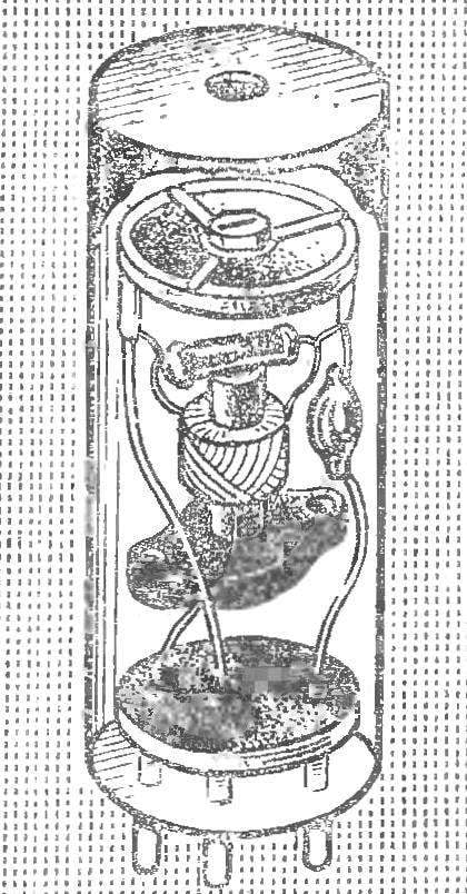
 To calibrate, to establish or verify the performance of the radio equipment in the frequency range of 1-75 MHz allows this device. His scheme (Fig. 1) comprises a generator-the”type” with capacitive connection is made to the transistor V1. The oscillator frequency and its harmonics determine the replacement of quartz resonators B1, connected via connectors X1—X3.
The V1 emitter connected to the base of transistor V1 to serve as amplifier-limiter HF oscillations. In this way increase the amplitude of higher harmonics. The frequency spectrum of the output signal on coaxial socket X4, expands due to the unilateral constraint of the variable component of the diode V3.
Wiring diagram for resonators at frequencies below 2 MHz figure 1 shows the second color. The capacitors C1 and C3 are enabled in parallel, providing a stable excitation of the generator.
The calibrator employs resonators of various types, designed for 1-21 MHz frequency, including inactive.
П423 transistors can be replaced by П493, П403А, П416, П416А, П416Б transfer ratio current VST — 40-60. Coil L1 contains 5 sections with 150 turns of wire of winding 0,15 PALSO “universal on the frame Ø 6 mm. the Magnitude of its inductance is not critical, so it fit the contour coil far from any radio. The capacitors C1 — C5 ceramic — NTK or KTM, resistors R1, R2 — ULM, EU-0,125, MLT-0,25. S1 — toggle switch TV2-1. G1 element 332, 316, 343. X4 — coaxial socket on the TV.
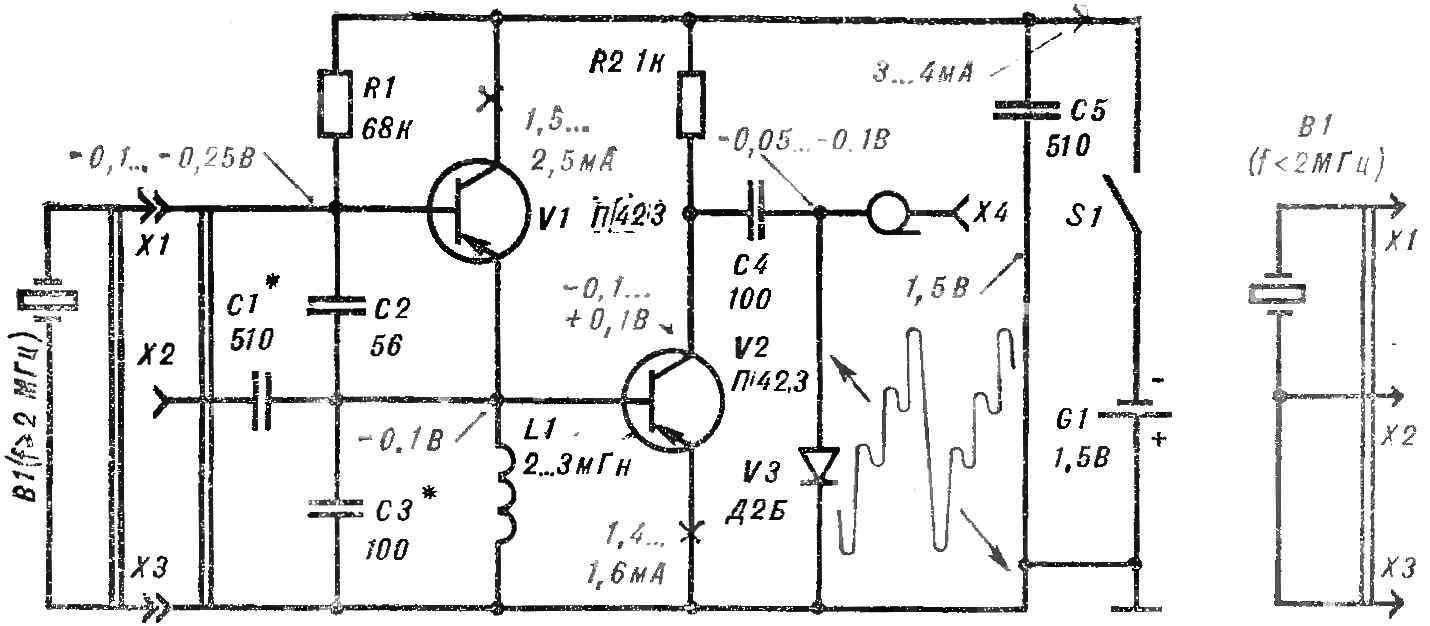
Fig. 1. Schematic diagram of quartz calibrator.
The calibrator is mounted on glinkovo Board size 85X50X2 mm and placed in a brass (or aluminum) body size 115X65X35 mm with removable lid. It has holes for access to sockets X1—X4.
Voltages and currents in the circuits of the calibrator measured by avometr Ц437 shown in the diagram (Fig. 1). To calibrate the antenna input of the receiver through the coaxial plug is connected to the socket X4 of the device and the power on. In the case that the fundamental frequency of the resonator or its harmonic coincides with the setting of the receiver, it reproduces a hissing sound (sometimes with a faint whistle).
To a sensitive radio receiver to connect the calibrator is not necessary: conductor of the plug is sufficient to bring to the antenna input.
To calibrate the transmitter to the socket X4 connect high-impedance headphones. If now the connecting cord closer to the transmitter antenna, the induced high frequency voltage will go ka diode V3. Due to the nonlinearity of its characteristics are between the oscillations of the transmitter and calibrator have runout. Listen to their tone in the phone, adjusting the transmitter frequency to the desired value.
Hams often not the right “quartz”. But you can do without them? Of course, the frequency stability of quartz resonators is much higher than the resonant circuits. In practice, however, the latter also give satisfactory results. Assuming of course that the elements of the circuit have a high q-factor.
Figure 2A shows a diagram of a circuit for a frequency of 1 MHz. The L1 coil contains 40+70 turns of wire LASO 10X0,07, winding “universal” frame of Ø12 mm.
The capacitors C1 and C3 to the CCP, C2 — NTC negative temperature coefficient of capacitance (red or blue).
In the circuit at a frequency of 10 MHz (Fig. 2B) is single-layer coil L1 consisting of 11 + 22 turns of wire sew 0.5, basted on the frame Ø 12 mm.
Design of replacement circuits for calibrator shown in figure 3. All the elements of both schemes should be rigidly fixed.
To configure the circuit (Fig. 2A) it is connected to the calibrator is connected to is configured for a 1 MHz receiver ( wavelength of 300 m). Setting the coupling capacitor C1 at maximum capacity, changing the value of capacitor C3 to the signal from the receiver. Then the capacitance C1 is gradually reduced to compensate for the detuning with C3, approaching the optimal value C1 to the value at which there is a failure of oscillation of the calibrator.
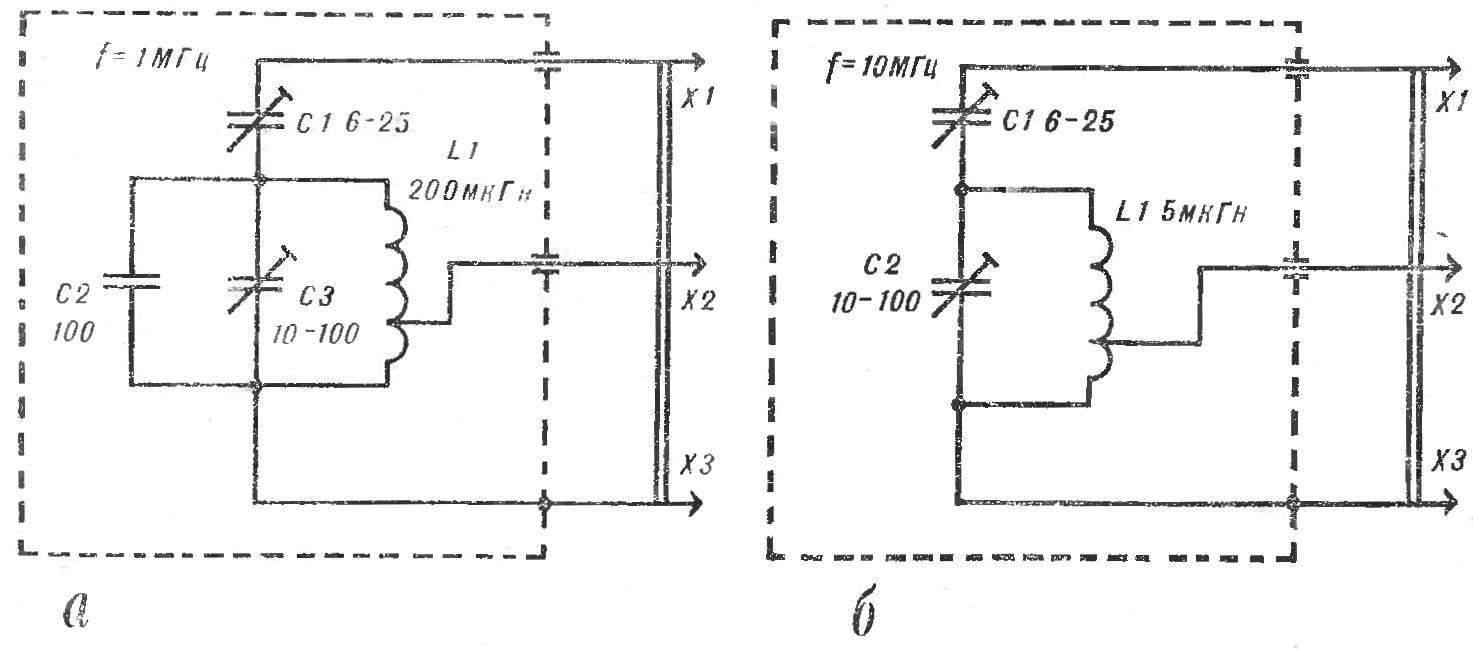
Fig. 2. Schematic diagram of the replacement circuit

Fig. 3. The changeable contour.
Setting contour specify by connecting to the receiver, the generator of standard signals or calibrator with quartz resonator. Achieve kulevich beating between the frequencies of the contour and model of the source, slowly rotating the rotor of the trimmer capacitor C3. (First get a high tone beat, then low, and finally the sound disappears, and this corresponds to equality of the compared frequencies or their harmonics.)
Similarly configures the second circuit (Fig. 2B), but the receiver in this case is transferred to a frequency of 10 MHz (a wavelength of 30 m).
There are other ways to fine-tune the contours of the calibrator, for example, by using an electronic frequency counter or oscilloscope and GSS. Such devices have in the laboratories of the radio clubs, Palaces and Houses of pioneers, syut.
E. ROMAN, Ivano-Frankivsk
Recommend to read
 Build your own voice amplifier
When I needed a megaphone, I looked at the prices of industrial Chinese products: as it turned out, they cost from $45 to $235, and I decided that I could assemble a similar device with my... THE CATAMARAN OF THE DAY
The easiest kayak in comparison with it will be two to three times heavier. Folded it is less than any inflatable boat. But to sail on the catamaran can be together, as on a good kayak....
