RADIOSONIC CONTROLS THE PUMP

RADIOSONIC CONTROLS THE PUMPThe creation of remote electronic devices control various actuators were promising direction in the radio even during my “pioneer” childhood in the 1980-ies. Then, under the guidance of mentors, we enthusiastically gathered such equipment using discrete components. She usually had a range of 5 — 6 m and it barely fits in the box size 300х300х150 mm. If it was possible to assemble at least a fortnight instrument remote control model boats or aircraft with a transmission range of teams at 20 — 30 m, it was considered from us (10 to 12-year-olds) with great success.

 
Not lost its relevance this direction today. But now it is easier to do because you can not assemble parts, and you can buy in the store ready device signal transmission by radio (using the IR channel, laser beam, etc.), and for a very “affordable” price and adjust personal goals to improve it.
 
Of course, it is regrettable that virtually nullified the creative part of the construction of the device, involving a painstaking understanding of the question of its operation — from design to configuration, not only enhancing skills, but also opens the door to deep fundamental research.
 
But, on the other hand, why waste time and “suffer” — to create a device from scratch if it is possible to improve ready, expanding its range. This approach is acceptable for professionals or those who need to obtain practical results of their work.
These are the realities of time and have reasonably flexible.
 
Invite readers to consider the remote control device acting on the air for a distance of over 100 meters and to automate the enabling and disabling pressure submersible water pump, supplying water in house, bath, barn and other buildings infield from the source — the village well.
 
The unit can be purchased in hardware store RadioShack wireless value-192 rate. In passing, I note that the finished equipment pump station control (without wires) is worth more than 3,000 rubles. Draw your own conclusions. However, it is capable of still further implement automatic monitoring of water pressure in the circuit when it decreases (open the tap in the house), commands the filling of the storage tank, and some models and water heating. But in our case these features were unnecessary.
 
Electrical circuit receivers radioshow
 
Schematic diagram of the receivers radioshow

 
Electrical circuit
 
The electric circuit of the consoles
 
Wireless calls may have a different appearance, but their composition is mandatory elements are the transmitter and the receiver. Typically, such wireless calls operate at a frequency of 433 MHz and do not interfere. Besides their power of the transmitter is small.
 
According to the manufacturer in the passport range purchased radiosonde is 50 m. However, in practice, this distance is much less, even if the transmitter and receiver are mounted in line of sight without any obstacles between them. As a rule, this figure should be divided by three.
 
With the increase in the stated range radioshow increases their retail price. For example, a wireless call with a radius of 100 m (in reality 35 m) is already more than 1100 rubles. But such purchase is not necessary — after all, Amateur radio is, in fact, still, what call to improve, developing his range. Therefore, we consider the easiest “budget” option.
 
The first thing you need to remove the housing cover of the radio, because to increase the range of your will on it. Its antenna will not touch, because on a radio frequency 433 MHz, its length practically does not influence the increase in distance work, a link transmitter — receiver.
 
The photo shows the receivers of radio signals with the removed cover — two different appearance models. But the scheme they have one (p. 21), although performance on the PCB is different, in particular, on one of the photos presented, assembled from discrete elements and the other elements in the SMD housings for surface mounting.
The terminal 2 of the chip U1 has an active high level when receiving a radio signal from the receiver (when it is pressed). Conclusions 1 and 8 of U1 on the contrary: high level — at rest, while a low logic level upon receipt of the control signal. These two signals can be used to control the load devices with the help of simple consoles.
 
To the remote pump start to work effectively (the first press of transmitter button connected the pump to the network 220, and again to turn it off), you will need to assemble a simple additional device and connect it to circuit (Board) of the receiver, industrial wireless call.
 
The improvement of the receiving node
 
The diagram (below) is a circuit diagram of a prefix (optional device) receiver of the wireless call.
 
Parallel to the lamp filament ЕL1 connect a submersible pump (not shown in the diagram) with a matching reinforced hose, which stretches to the house from the well. ЕL1 lamp is an additional light indicator of work of the pump, it is possible to verify that the command is received from the transmitter, the remote worked, and the pump came on.
 
The output of the STB connects to the underlying PCB receiver radiosonde unshielded wires type MGTF-0,4 (or similar), it connects the common wire (less power) and terminal 3 of the element chip DD1.1 (K561TM2) to the output 2 chip CD4069BD (in some models D4069UBC). Domestic analogues of these chips — КР1561ЛН4 and К561ЛН5.
 
When receiving a radio signal from the transmitter (its duration — about 2 is provided with a transmitter-keychain regardless of duration of exposure on its button) on the output 2 chip CD4069BD (U1), the signal level changes from low to high. The terminals 6 and 7 of the chip U2 is a generator of tunes connected to a low-power dynamic head.
 
Thus, in order during signal transmission via radio is not included melodic call, is enough to tear the printed conductor from pin 7 of U2 to a dynamic capsule. Or unsolder one wire leading to it.
 
Electrical circuit transmitting node radiosonde
 
The electric circuit of the transmitting node radiosonde
 
The basis of the device is the trigger on one element of popular chips K561TM2. Without going into the details of her work (it is written a lot of articles), most important note: in this chip, two D-flip-flop comprising two input asynchronous control S and R. the Trigger is switched by the positive differential clock input (a conclusion of 3 DD1.1). At the same logic level present at the D input is transferred to the direct output Q. When a high logic level on the reset input R of the trigger reset. The supply voltage can be in the range of 5… 9 V (about the experiment to increase the voltage of the receiving node below).
 
Now, knowing the chip DD1.1, it is possible to understand the General principle of operation of the device. When the power at the input R DD1.1 the first time through the discharged capacitor C2 goes to a high logic level, which resets the trigger on the direct output Q is set to a low voltage level. Transistor /T1 closed, relay K1 is de-energized, ЕL1 lamp is not lit, the pump is not working.
 
About a third of a second (this is due to the capacity of electrolytic capacitor C2 and resistor R1) of the first charged almost to the supply voltage, and the input R (terminal 4 DD1.1) will change to low. Now the trigger is ready to receive signals at clock input C, which, according to the scheme, low initial level.
 
When the radio signal from the transmitter from the receiver is input With the chip DD1.1 is the layout of the remote call goes to a high voltage level. As a result, the trigger being transferred to another stable state — now at its direct output Q a high level voltage. Transistor VT1 operates a relay K1 and its contacts in turn, closes the electric supply circuit of the lighting lamp EL1 and the submersible pump. In this state, the trigger is arbitrarily long, until the next positive edge of the pulse at the input at entry (next key on the remote control transmitter) switches the trigger to its original state — ЕL1 illumination lamp goes out, the pump is de-energized and turns off.
С2R1 circuit provides a reset trigger circuits DD1 to the original standby when the power is turned on. Oxide capacitor C1 performs the function of the filter element for nutrition. The VD1 diode prevents the reverse voltage surge at switch-on/off of the relay.
 
The total capacity of the switched load depends on the parameters of electromagnetic relay K1 and in our case limited to 350 watts.
 
Since the number of discrete elements of the console are small, all of them mounted on a perforated Board plot size 30×40 mm and together with connecting wires are placed in a regular receiver remote call to the compartment for elements of Autonomous power. To reduce the impact of electrical interference it is desirable that the wires connecting the device with the power source and going from relay K1 to the pump, had the section not less than 1.5 mm and a minimum length.
 
Details
 
Fixed resistors MLT-0,25 (MF-25). Electrolytic capacitors of the type K50-26 operating voltage at least 16 V. the Remaining non-polar type capacitors KM-6B. The chip DD1 (K561TM2) can be replaced К561ТМ1 without compromising the efficiency of the node, but in this case, you will have to change the schema, because the conclusions of these chips have different purposes. Information about this replacement option can be found in reference books on modern CMOS chips. Transistor VT1 — field, with high input impedance. This allows to minimize the leakage current in the standby state of the radio signal and almost no effect on the output of the trigger, despite the limiting resistor R2 with a low resistance.
 
Relay K1 can be replaced РЭС43 (performance RS4.569.201) or more, calculated on the trigger voltage of 4…4,5 V and current 10…50 mA. To set the device relay with switch-on current more than 100 mA is undesirable, since the gate of the relay transistor VT1 has a finite capacity.
 
Receivers radioshow with removed covers Receivers radioshow with removed covers
 
Receivers radioshow with open covers:
 
and — from a discrete element; b of the items in the SDM-buildings

 
Instead КП540А you can apply a field-effect transistor is any of a series КП540 or its foreign counterparts BUZ11, IRF510, IRF521. Led НL1 any, it is convenient to control the relays and the circuit contacts of the Executive. If necessary, the elements Ni and (R3, you can exclude from the scheme without consequences. Additional (manual mode) the pump switch in the diagram shown under the designation ЅА1.
 
The coil L1 is frameless with 4 mm diameter from a 1.5 round silvered wire in diameter 0.8 mm (turn to turn). The choke L2, type D-06 82 µh inductance (microhenry).
 
In the basic version provides a self-powered — 2 AA element at 1.5 V. But in the conditions recommended the use of remote call is best done stationary powered by a stabilized power supply with 5 V voltage with deviations not exceeding ± 5%. Such a source can be, for example, the stabilizer on the chip КР142ЕН5А. The current consumption of the transmitter in active mode 35 mA. The current consumption from the power source of the receiving node in constant standby mode does not exceed 10 mA and increases to 50 mA when enabled, is specified in the relay diagram. Other types of relays the current consumption can have a different meaning.
 
Attention!
 
The optimal supply voltage of 5-9 V. receiver to Increase the voltage of the receiving node is not necessary, because the range of the device, this innovation does not increase (tested experimentally by bringing the voltage up to 12V).
 
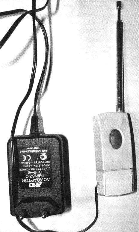
The transmitter itself, outwardly representing the body in the form of a key chain the size of a standard matchbox, the finalization is not needed. Not to change once a year battery (the same kind installed in most transmitters, key fobs security alarm system for cars — 12V 23АЕ, the manufacturer GP Ultra or similar), the power of the transmitter is carried out using an industrial adapter with the output stabilized voltage of 12 V and a current not less than 0.5 A, such as the type of TV-182-S.
 
The tuning coil L1 with a shutter core inside. The diameter of the outer coil of 4 mm, coiling 5 turns of the silvered wire in diameter of 0.8 mm.
 
L2 — choke type D-06 inductance 82 CTG.
 
The transmitter antenna is worthy of detailed description. To increase the range of operation to the antenna contact on the circuit Board with pigtail MGTF-0,8 (or similar) solder telescopic whip antenna for radios (available in stores). Or, at least, what is incomparably worse — to use as an antenna similar to the regular stranded wire with a length of 350… 400 mm, fluffed at the end, like the petals of a flower, thin wires (diameter of “flower” — 60…80 mm).
 
Greatest range of work with a telescopic antenna (in practice) will be the case when the “telescope” was nominated to the middle, that is the same on the 350… 400 mm.
 
Now, assuming the recommended improvements of the antenna in the transmitter device fails to range up to 200m in line of sight and remote control motor pump or other resistive load, the choice of which is limited by the parameters of the actuating relay and imagination of the author.
 
A. KASHKAROV, St. Petersburg

Recommend to read

  • STARTS… CARDBOARDSTARTS… CARDBOARD
    Going into the club "Technical modeling", we saw a lot of bench models made of paper and cardboard by One of our members suddenly suggested — and in fact the GAK you can build and...
  • FRIGATES AND CORVETTESFRIGATES AND CORVETTES
    Not to say that after the First world war, the British did not think about the problems of a future war, but their reasonable ideas are embodied in a metal surprisingly slowly. For...