
 The proposed remote control system (remote control) is executed in the form of attachment to the radio commercial production. It allows you to control ten different loads with up to eight fixed channels (the first pressing — on, second — off) and two not fixed (the operation is possible only when the button is pressed).
A basic phone can be used for its intended purpose: to communicate with users in normal mode (with pulse dialing), whereas with remote control works tone. In principle, it is not forbidden tone dialing and subscriber connections, if you temporarily do not use the retry button (with the image of the “stars”).
The actual range of the remote control is determined by the range of stable radio communication between the base unit and portable handset.
This system can be used by people with mobility disabilities to turn on and off lights, electrical appliances (heaters, fans, etc.) to unlock electric door lock (this uses the push channel DU). Well, if you have a basic cordless phone long range easy to create the effect of the presence of the owner in the apartment, scaring off intruders.
Modern cordless phones transmitting tract, usually performed at a high level — with the use of frequency modulation (she provides high noise immunity) and double frequency conversion. The main signal amplification happens at the second intermediate frequency, a first intermediate selected sufficiently high, for increased selectivity on the mirror channel.
Typically, the receiving and transmitting paths are used in frequency synthesizers with quartz stabilization or adjustment of equipment is carried out by using the so-called PLL. More complex and expensive models of cordless phones scan all channels of communication and allow you to automatically tune in to free or on stable channel with a lower interference level.
All current models of radio telephones are equipped with a system of coding compliance compact handset and base unit (ID-code). This is a pretty strong protection. The gist of it is that laying the tube on the base unit both parts of the instrument together choose one of the pre-specified ID codes, and further communication is possible only between speakers of the same password. The number of such telephone ID codes varies from a few tens to a million.
Usually for a small number of ID codes in the base unit is installed specific for this cordless version of the code using a set of jumpers or dip switches. Their position is read by an embedded controller. When the handset is placed on the base unit, the ID code is transmitted to the receiver, and then automatically set their mutual consistency.
Expensive cordless phones provides a large number of ID codes stored in the ROM of the handset and the base unit. Compared to other models, it is a distinct advantage. Each time lowering the tube to the base unit selects a new ID-the identification code of the tube. The possibility of using a stranger here portable tube is practically reduced to zero.
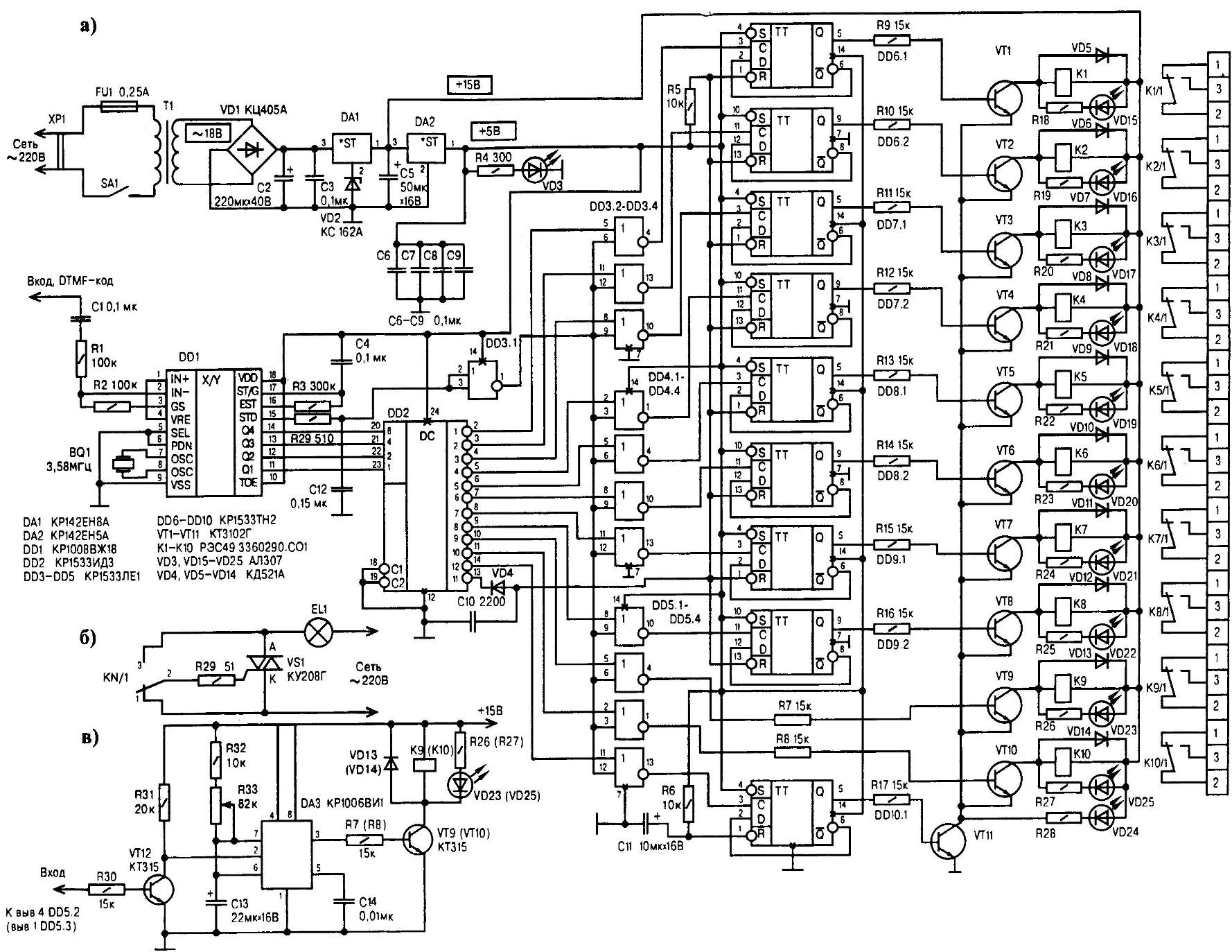
Circuit diagram of remote control system (a) on the basis of “branded” phone with the possible use of improvised triac electronic keys (b) and the pulse extender (in)
Now a little bit about telephony. To establish a connection with the subscriber can use pulse or tone dialing. The calling telephone apparatus when the set pulse which will short the telephone line mechanical (movable contacts) or electronic key. That is, in ATS generated voltage pulses, whose number corresponds to the dialed digit.
When the tone (tone) dialing the calling telephone generates audio frequency. It is very important that they do not go beyond the audio spectrum. Increases immunity, reduces the time of set, moreover, offers added convenience.
In devices with tone dialing to use two groups of frequencies: lower (697, 770, 852 and 941 Hz) and upper (1209, 1336, 1477 and 1633 Hz). Each figure or official symbol corresponds to one frequency from the lower group and one from the top (here all possible 16 combinations). So when you click on patchbay any of the buttons generated dual-frequency (dual tone) signal, the so called DTMF code.
The basis of the system control (Fig.a) is the receiver DTMF chip КР1008ВЖ18 (analog — MV8870). Performed by the CMOS technology, it contains the input differential amplifier, filters, upper and lower groups of frequencies of the switched-capacitor clock generator circuit for digital signal processing, decoder and bus interface for registers-latches with three States.
Inputs IN+, IN- (pins 1, 2) chip КР1008ВЖ18 are inputs of the differential amplifier. The output GS (3) there is nothing like the output of the differential amplifier(used to set gain) and the output of VRE (4) — output internal voltage reference. Input SEL (leg 5) is selection code table (for MV8870 two possible matching DTMF-sending the output code) and the entrance PND (6) — translating into reduced power mode (for MV8870).
The OSC inputs (pins 7, 8) chip КР1008ВЖ18 or her foreign counterpart are used to connect external quartz resonator, VSS (9) is the “common wire”, and TOE (10) input signal resolution output data. The legs of the chip, labeled Q1— Q4 (findings 11-14), serve as data outputs with three-state STD (15) is the output signal of late detection, EST (16) output signal for early detection, and the output ST/G (17) — bidirectional output control signal duration and pause. Finally, the VDD input (pin 18) is intended for connection to “plus” the line of supply.
The chip used in the standard inclusion, i.e., its internal differential amplifier operates in the mode unity gain, the voltage supplied from the output of VRE, shifts the output of the amplifier to the level of VDD/2.
Amplifier output signal is fed to a block of bandpass filters, where the separation of the upper and lower groups of frequencies. Going after these filters, the digital processing circuit detects the frequency components and compares them with the standard DTMF frequency signal.
When the decoder responds to the simultaneous presence of both the allowed frequencies (as “signal” mode), the output of the early detection of EST goes into an active state (log.1). In the absence or sudden disappearance of the signal mode output EST will be deactivated.
After detecting the DTMF signal to verify its presence within the minimum allowed time interval. This is done with the help of external time-setting RC-chain is connected to the output EST. The emergence of high-level (log.1) at the output of EST causes the voltage increase on the output ST/G due to overcharging of the capacitor.
If the detected signal retains its parameters (output EST is held the log. 1 ) within the time specified by parameters of the RC-chain, then the output ST/G reaches the threshold level control logic. Is then receiving the tone pairs and the output registers latch is written to the corresponding 4-bit code.
After a short delay, needed to establish the values of the output registers, the output of late detection of STD is set to high level, indicating that the new code adopted by the sending DTMF signal is available to be read. Following this, when applied to an enable input of TOE the logical unit is issued, the contents of output registers on the output bus (Q1-Q4).
In case of DTMF input, the control circuitry checks for a valid inter-symbol pause, working in reverse order. Thus, the chip does not accept DTMF signals shorter than the valid duration, and does not account for the disappearance of the signal at a time that is less than acceptable inter-symbol pause.
From the output of the DTMF receiver-signal (chip DD1) code adopted by the parcels sent to the inputs of the decoder DD2, introducing the corresponding output to active state (log.0). Outputs 1-10 (findings 2-11) of the decoder are used to control ten channels. As a memory element for the fixed channels used triggers DD6—DD9.
When the button is pressed a fixed channel (the numbers 1-8 on the keypad of the handset) on one of the outputs (1-8) decoder appears the active level (log.0), which will be one of the top (the scheme) of the inputs of the valves 2 OR NOT (DD3.2—DD3.4, DD4, DD5.1). Another thing, if is pressed button push channel (figures 9, 0 on the keypad of the handset). In this case, the active level will be on one of outputs (9 or 10) decoder and one of the top (the scheme) of the inputs of gates DD5.2, DD5.3. On the lower inputs of all of gates comes the inverted and buffered signal STD from the output of the valve DD3.1.
Thus, after receiving the DTMF-sending the output of DD3.1 set log.1, opening the valve, to the second input of which receives the active level from the decoder. At the output of the open item set log.1. The positive difference, resulting at the same time, sets the output of one of the triggers DD6—DD9 status log.1, if you pressed one of the buttons fixed channel. Pressing the same button on the trigger output is the log.0.
The signal from the triggers (and logic elements DD5.2, DD5.3) arrives at the inputs of electronic keys made on the semiconductor triode VT1—VT10 with the electromagnetic relay, switching the load directly (or better relay). In the collector circuits of these transistors are LEDs VD15—VD25 indicating the status of channels.
As keys for controlling, for example, light sources are quite acceptable and triacs (Fig.b). With installation on radiators maximum load current can reach 5 A.
In earlier models of cordless phones the tone duration of the parcel is determined by the duration of pressing the button set. Have modern equipment (for example, GSM-900) it is fixed to 40 MS. When you use these (and later) models as the base for the system do not do without the extender pulses (RI) in an uncommittable channels.
In particular, stable and high performance shows RI based on the circuit diagram which is the integral timer КР1006ВИ1 (Fig.in). The original impulses it receives from the logic element DD5.2 (DD5.3). Chip КР1006ВИ1 works in standard is one of a vibrator without restart. Chain R32R33C13 determines the pulse duration at the output of the timer to change where in the range of 0.2—2 serves as a variable resistor R33. As C13 is better suited oxide-semiconductor, tantalum, or the like, having compared to aluminum capacitors, more stable options. Transistors VT9 (VT10), VT12 — low-power bipolar, having the structure n-p-n.
Before working with the system do need to switch to tone dialing by pressing “*” or transfer switch PULSE-TONE in the TONE position. Then you should press “*”. Thus the output 11 of the decoder is active, which through the diode VD4 installs the direct outputs of the triggers DD6—DD9 to its original state. So you can reset all latched channels.
Next, press the “#”. Thus the output of decoder 12 is set to the active level, which is accompanied by a transfer trigger DD10.1 in the status log.1 at its output. The transistor VT11 is opened, connecting the “common wire” key channels of the same power wire. When you press the “#” is a connection stops working, i.e. all channels are set to the original state, reducing the likelihood of accidental management. The luminescence diode VD24 indicates the entrance to do. Chain R5C10 R6C11 and when the power transferred all triggers in the initial state.
Chain R29C12 provides a signal delay of the STD, which is necessary for the correct operation of the triggers fixed channels. If a chain was not, after a common reset capacitor C10, razladilis through the diode VD4, did not have time to charge to the switching threshold by the time of arrival of a positive edge on the clock input of a selectable trigger.
The power supply is assembled according to the traditional scheme and has output two voltages: +5 V (to power the digital part of the circuit) and +15V (power transistor switches). In the “common wire” 9-volt stabilizer DA1 includes a Zener diode VD2, to raise the output voltage to 15 V. the Led VDЗ for display on the device. Capacitors C6—C9 interlock, installed in the vicinity of digital circuits. Well, the transformer T1 provides at the ends of the secondary winding of the 17-18 Century.
DTMF is best to remove the IC output base unit (not telephone line). The desired output is easily found by using the oscilloscope: press any button in the tone mode, it is only necessary to probe all the pins of the chips. The tone signal has an amplitude of 1-2 V and a characteristic shape similar to the shape of the balanced-modulated signal with small frequency spacing.
In the device, it is desirable to use integrated circuits series КР1533 ( DD2—DD10). But they can be replaced by similar types of КР555. Capacitors C3, C6—C10 ceramic, for example, KM-6; C2, C5, C11 electrolytic K50-35, and as C13 will fit K53-14. Resistors — C2-33-0.25 (of course, you can use C2-22, MLT and other small-sized counterparts).
Diodes VD4—VD14 series KD521, but there are other silicon switching counterparts. The diode bridge VD1 — КЦ405А. Zener diode VD2 — КС162А. LEDs VD3, VD15—VD25 is desirable to have a series АЛ307.
All the transistors shown in the circuit diagram of remote control system, КТ3102Г, although it is also applicable with other silicon n-p-n structure and a gain current of more than 200. Triacs — КУ208Г. Relay — РЭС49 (passport 3360290.0001) with an operating voltage of 27 V (all instances available from the author, worked at 10.2 V, so called headroom voltage sufficient for stable operation of the system control). Quartz crystal resonator with a frequency of 3 579 545 Hz (used in NTSC decoders-signal).
V. VASILENKO, Sverdlovsk, Luhansk region, Ukraine
Recommend to read
 LITTLE MICRO-CAR “BUDDY”
Little micro-car "Buddy" machine... for kids. It was created in a laboratory experimental simulation and design Club for young technicians Novosibirsk Akademgorodok. Despite its small... SNUFF PIPE
Among smokers at all times, alone stood out, those who prefer tubes. This is due not only to the dubious assertion that the pipe is less harmful, but solemnity in the ritual of tamping...
