 Revision of power supply EPS-35. Every radio Amateur, equipping a workplace, in its own way solves the problem of providing it with power supply (SP). Some prefer powerful UI with an output current 10 and 20 a, And someone is satisfied with a simple and low-current (up to 2). The taste and color, as they say, no friends. From my point of view, home laboratories should have a SP with output current not less than 5 and the overload protection on the output.
As one of the options as the basic design, you can use a commercial (ready-made) sources that are sold in stores. But most of them have a drawback: the output voltage is not regulated. It is easy to eliminate due to small changes in the schema SP, and to make that even an Amateur with little experience.
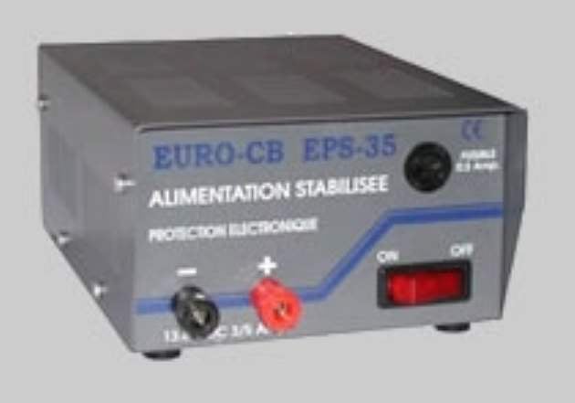
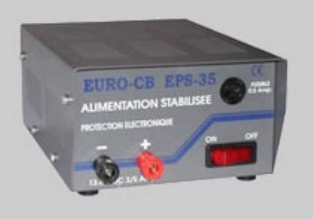
For example, a simple industrial entrepreneurs, used by Amateur radio operators-hams (Euro SV EPS-35) to power automotive and portable transceivers, can be slightly modified so that this guy had the adjustment for the output voltage, and if necessary, the adjustment of the threshold protection is enabled. The photo shows the modified device with the additional output voltage regulator (the black knob on the front panel).
The PI is available in two versions: with output current up to 5 A output current up to 7 A. the Indication of the specific device type is available in the documentation and on the case of IP—down front panel (terminals). The output voltage on the passport 13.2 V ±5%.
Power node PI is performed by the classical scheme: two secondary windings II and III give a variable voltage to 18 V, it is rectified by the diodes VD1 and VD2 and smoothing the oxide capacitor C4. From its parameters, as well as from the parameters of the capacitances C6 and C7 depend on output ripple voltage (in this case the passport does not exceed 400 mV). Transistors VT1 and VT2 are included in the Darlington circuit, made the power node control voltage (VT2 installed on insulated from the body of the radiator).
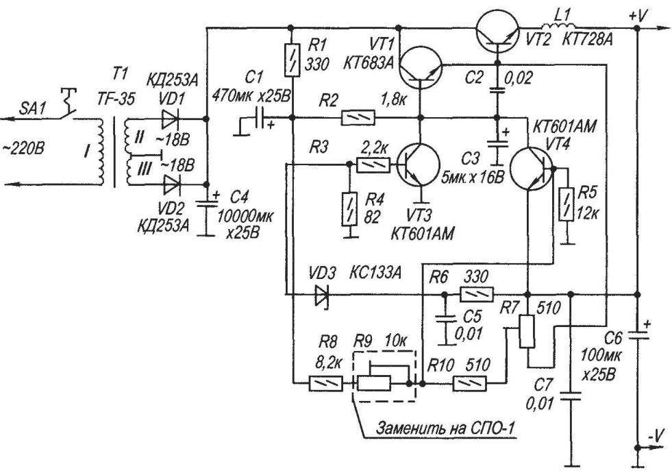
Schematic wiring diagram power supply EPS-35 variant of its modernization with the aim of providing adjustable output voltage
Wire coil L1 consists of 4 turns of transformer wire PEL-1 with a diameter of 1 mm. Its necessity is justified by the current overload. The voltage drop across L1 in the case of an overload controls the node of the transistors VТЗ, VТ4, which adequately reduces the potential at the base of the transistor VT1 and the output voltage drops. Protection is triggered when the output current of 5.5 A (for the device EPS-35—5). Slightly adjust the threshold protection is enabled, you can change the resistance of the resistor R7 is rigged. To adjust the output voltage of the reference design used a fixed resistor R9, which should be replaced with a variable resistor SPO-1 (or similar) and a pen display on the front panel of the device. At minimum resistance the output voltage will be 15 V and with maximum output voltage will fall to 5.8 V. the Converted power supply is now able to address the broader needs of Amateur radio testing and establishment of different devices from low-voltage power supply 6…15 V.
Similarly, it is possible to improve power supplies from other manufacturers. To collect considered entrepreneur yourself, ham radio operator may require information on changes of the main elements of the scheme. VD1, VD2—КД253Б, Д231—D245—with any alphabetic index, 2Д230Ж—2Д230И, 1N5401. VT1 — КТ723А—КТ723Б, Т1Р31. VT2—2N3055 (with current up to 3 A can be set КТ819ГМ). As VТЗ, VТ4 used КТ601АМ, КТ605АМ—КТ605БМ, КТ630Д —КТ630Е, КТ610А, 1КТ610Б, D882NL. Electrolytic capacitors K50-24 or similar.
A. KASHKAROV, St. Petersburg
Recommend to read
 FROM SPANNER — RATCHET
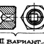
I propose to use a wrench as nidificantes in our time knob to operate the taps and plumbing expansions. This steel hexagon need to make an adapter with a square hole corresponding to the... SELF-PROPELLED PLOW
By itself, the plow actually riding. But it has become possible to plow without a horse due to all the same self-propelled chassis, which we used for the potato digger. This unit is...
