
The metal detector I designed operates on the beat frequency principle, which arises from the difference in oscillations between the reference and the tunable oscillators (typically the 5th–10th harmonic, whichever is closest in frequency). This design allows the detector’s sensitivity to reach a level where it can detect, for example, a five-kopeck coin buried 10 cm deep, or a steel manhole cover or pipe at a depth of 65 cm. Built with readily available components, the detector requires no fine-tuning and is easy to use. Power is supplied by a 9V “Krona” battery.
The tunable oscillator is built using the so-called “capacitive three-point” circuit on logic elements DD1.1 and DD1.2 of the domestic IC K561LA7. Its resonant circuit is formed by the search coil L1, capacitors C2–C4, and varicap VD1. The required voltage for tuning the varicap is provided by the potentiometer R2, which acts as a tuning control for adjusting the beat frequency.
An additional transistor VT1 is included in the circuit to provide temperature compensation for the varicap VD1. If the metal detector is to be used under favorable conditions, with minimal ambient temperature fluctuations, VT1 can be omitted.
The reference oscillator is implemented on two NAND logic gates of the DD2 (K561LA9) IC. The frequency is stabilized by a quartz crystal resonator ZQ1 (1 MHz).
Both the tunable and reference oscillators include buffer stages (logic elements DD1.3 and DD2.3, respectively), which feed into the mixer DD1.4. The resulting difference frequency signal is sent to an amplifier (transistor VT2) with an emitter follower (VT3). The audio indication of metal detection is provided by the BF1 microtelephone capsule from a hearing aid. The voltage regulator DA1 supplies the electronics with a stable 5V, while diode VD2 protects the circuit from reverse battery polarity.
The tunable oscillator is adjusted to the desired 100–200 kHz range by selecting capacitor C2 and changing the capacitance of trimmer C3 with the potentiometer R2 set to its mid-position. The goal is to achieve the loudest possible beat tone in the BF1 capsule when the oscillator frequencies are close.
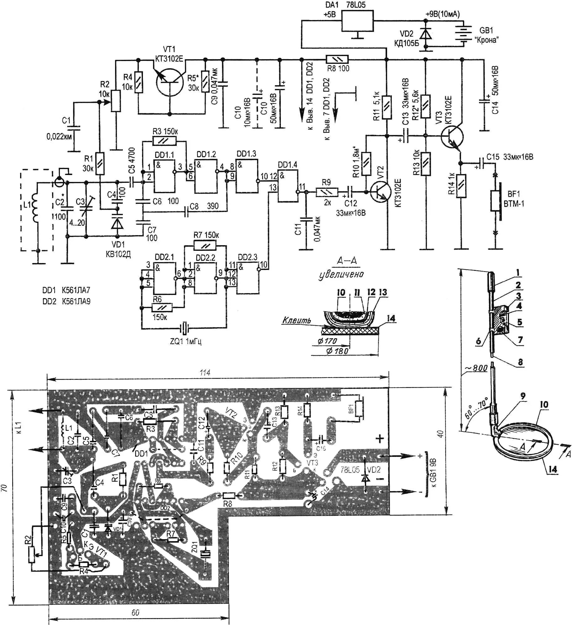
1 — handle; 2 — carrying rod (fiberglass ski pole, L900–1000); 3 — metal housing of the electronic unit; 4 — “Krona” galvanic battery; 5 — printed circuit board with mounted electronic components; 6 — mounting bracket for the housing (2 pcs.); 7 — “Tuning” control knob; 8 — coaxial cable; 9 — bracket; 10 — search coil (Ø160 min, 60 turns of PEL-0.2 wire); 11 — insulating winding (electrical tape layer); 12 — electrostatic shield (loosely wound aluminum foil strip, ends left unconnected); 13 — protective winding (2–3 layers of tape); 14 — base (fiberglass plate, 2–4 mm thick)
The amplifier with the emitter follower is adjusted by selecting resistors R10 and R12. As a reference, you should have about 2.5V at the collector of VT2 and at the load resistor R14. The temperature compensation circuit using transistor VT1 is tuned by adjusting R5, ensuring that the voltage between the collector and emitter of VT1 remains within 2–2.5V.
The search coil L1 is wound on a 160 mm diameter form and consists of 60 turns of PEL-0.2 wire. It is then wrapped with a single layer of insulating tape. After that, the coil is loosely wound with a serpentine strip of aluminum foil for electrostatic shielding. Electrical contact between the ends of the foil is not allowed, as this would create a shorted turn.
The resulting loop sensor is wrapped with two or three additional layers of insulation tape for protection, glued with epoxy (type EDP) to a 2–4 mm thick fiberglass disk base, and attached via a bracket to the carrying rod — a fiberglass ski pole with handle and control block. Inside the housing, the “Krona” battery and all electronics mounted on a 1.5-mm fiberglass printed circuit board are placed. The connection between the search coil and the circuit board is made with a coaxial cable running inside the carrying rod.
Now for the electronic components required to assemble the metal detector. All of them, including semiconductors and ICs, are inexpensive and widely available. The fixed resistors are of the MLT-0.125 type. For potentiometer R2, any compact model with a built-in switch will work (the switch is not shown on the schematic).
Fixed capacitors C1, C9, and C11 can be any small-sized type, as long as their capacitance values match the schematic.
More stringent requirements apply to C2, C4–C8: for reliability and long-term stability, these should be thermally stable capacitors. The trimmer capacitor C3 should preferably be ceramic, as it is more resistant to sudden temperature changes (for example, type KT4-23, 4–20 pF). For the higher-capacitance capacitors C10, C12–C15, you can safely use K50-6 electrolytics, which ensure stable circuit operation.
Using this component base, the author built several metal detectors according to the above design. It is pleasing to note that no difficulties arose during setup or operation.
“Modelist-Konstruktor” No. 1’2004, V. Grichko
Recommend to read
 “MOSQUITO” WITH FEATHERS
Among purchase toys that can move (ride, swim, run, fly, crawl), it is not easy to find such models that can be safely run in the apartment without fear that they'll break, dropping to... RELAY HALF-TRACK VEHICLES
Lenin in Gorki near Moscow in the spacious garage, which is included in the exposition of the House Museum of V. I. Lenin, it is an unusual machine: instead of rear wheel rollers with...
