
 To debug transistor-based hardware is much easier if you have the regular store stable voltages. Two adjacent shoulders of the bridge rectifier V1, V2 connect the unit Zener diodes V3 — V8 and V9—V14, V15 — V20, V21 —V26 or V27 — V32 (Fig. 1) exercising, in addition to rectifying the current, stabilization of the output voltage 7, 8, 9, 10, 12, 14, 16, 18, 20 or 24 V at a current of 30 mA. When the input voltage is within 110 — 240V output changes by 0.2 V and the current is 1 mA.
The rectifier is not afraid of short circuits in the load circuit. Open the load circuit causes the heating of the Zener diode, not exceeding, however, the permissible value.
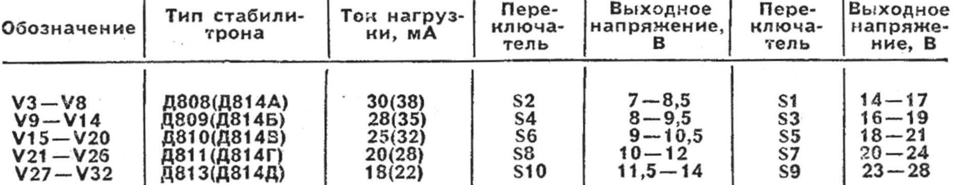
Due to variation of parameters of the same type of Zener diodes, they should be selected when configuring the device. (The values of the switching voltages depending on the types of Zener diodes and with the spread of their parameters are given in the table.)
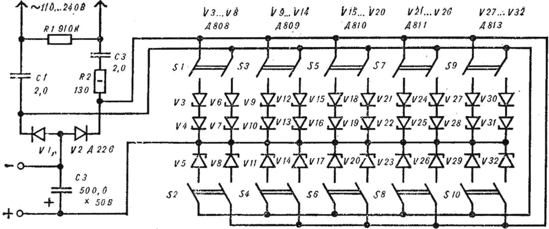
Fig. 1.
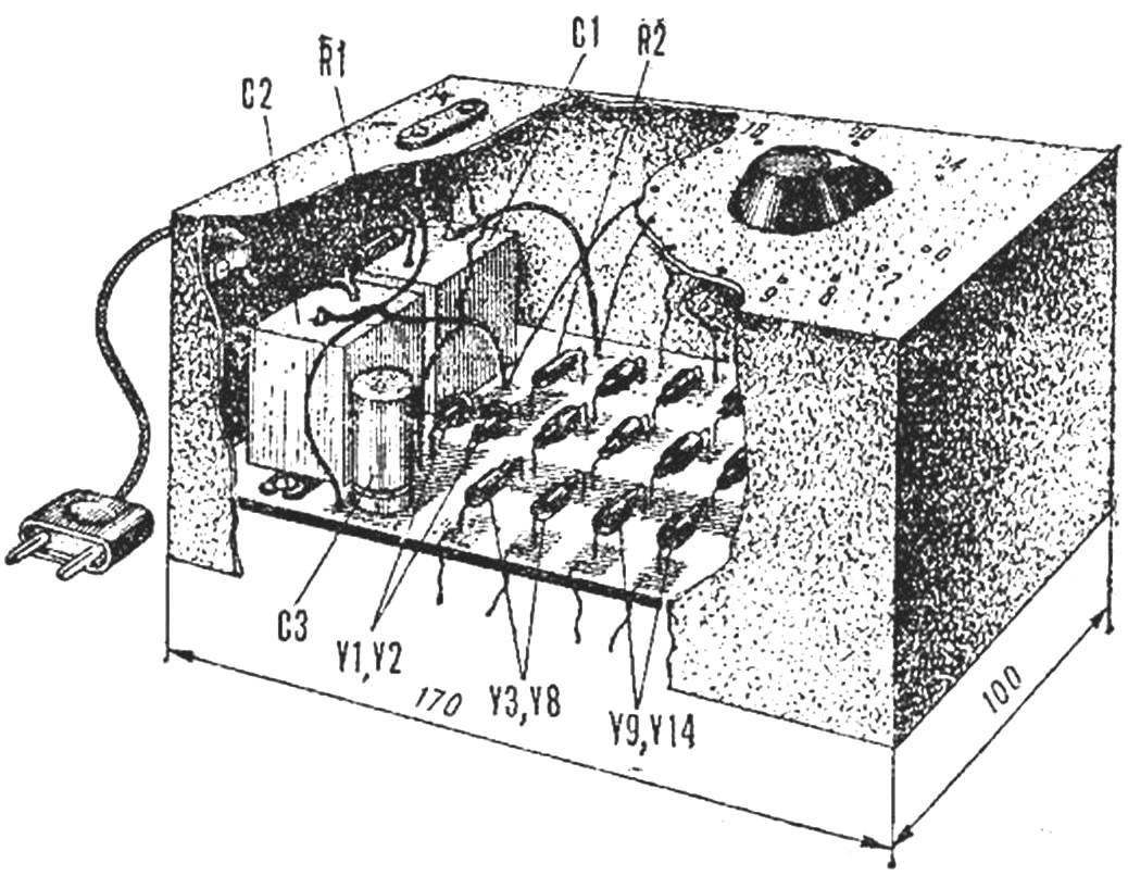
Fig. 2.
The design of the device shown in figure 2. Instead of Zener diodes, indicated in the diagram, it is possible to apply others: Д814А (V3 — V8), Д814Б (V9 — V14), Д814В (V15 — V20), Д814Г (V21 — V26), Д814Д (V27 — V32).
Capacitors C1, C2 paper at 400 V, Sz — electrolytic. The switches S1 — S10 — П2Г.
Recommend to read
 TACTFUL CUTTER
For more than twenty years a reader of "Modeller-designer". Thanks to the magazine made a lot of operational machinery: mini tractor, tillers, circular saw, trevaresse, welding...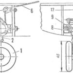 GEAR UP!
Ask any kid, building the first schematic model of what he wants Almost certainly he will answer — about copy. And it is clear. It's no wonder it is believed that the replica model is...
