SIMPLE RECEIVERS ON TRANSISTORS

SIMPLE RECEIVERS ON TRANSISTORSFirst steps in radio, many often begin with independent fabrication of a transistor radio. Along the way, introduces the electronic components, acquired the skills in installation and work with measuring devices. And achieve rapid practical results is to the same positive stimulus for further study of fundamentals of electronics, gives confidence in their abilities and capabilities.

 
We offer to your attention a number of receivers of direct amplification of various degrees of complexity. However, the sensitivity and selectivity they are inferior to superheterodyne, but Masha receivers it is easy to collect and organize, for they do not require sophisticated equipment and scarce items. Take them to local radio stations operating in the bands long and medium waves.
 
First, consider the principle of operation of the receiver diagram is shown in figure 1. The treble booster is made of two high-frequency transistors V1, V2. UHF applied to a negative feedback DC current through the resistor R3. Through it is supplied and the bias voltage at the base V1 (removed from resistor R5). The use of resistors (R1, R4) in the collector circuits of UHF makes it more uniform increase in range and reduces the probability of self-excitation of the receiver. For this purpose serves as a filter R9, C5.
The low-frequency amplifier assembled in the five transistors of different structure. V4, V5 — pre-ULF. The power amplifier (V6, V7, V8) — transformerless, push-pull, automatic balancing half the supply voltage at the midpoint of the output stage. Through resistor R15 introduced a positive feedback voltage.
 
Fig. 1. Schematic diagram of radio with seven transistors: V1, V2 П401 — П416; V4, V5, V7, V8 МП39 — МП42; V6 MP35 — MP38; VЗ, V9 Д9Б, Д9Д, Д9Е.
 
Fig. 1. Schematic diagram of radio with seven transistors: V1, V2 П401 — П416; V4, V5, V7, V8 МП39 — МП42; V6 MP35 — MP38; VЗ, V9 Д9Б, Д9Д, Д9Е.
 
Fig. 2. Scheme ULF transistors of one structure.
 
Fig. 2. Scheme ULF transistors of one structure.
 
Fig. 3. The receiver circuit with the detector transistor.
 
Fig. 3. The receiver circuit with the detector transistor.
 
Fig. 4. The receiver circuit with five transistors: V1, V2 П401 — П4І6; V5, V6 МП39 — МП42; V7 MP35 — MP38; V3, V4 D9 with love letter index; T1 — output transformer from any transistor radio.
 
Fig. 4. The receiver circuit with five transistors:
 
V1, V2 П401 — П4І6; V5, V6 МП39 — МП42; V7 MP35 — MP38; V3, V4 D9 with love letter index; T1 — output transformer from any transistor radio.
 
Fig. 5. Location details pathtransition receiver in the case.
 
Fig. 5. Location details pathtransition receiver in the housing.
 
Fig. 6. The connection of the parts of the reverse side of the Board.
 
Fig. 6. The connection of the parts of the reverse side of the Board.
 
The establishment of the receiver is to install using resistors R15, R5, the collector currents of the transistors V8, V2 in accordance with the values specified on the schematic diagram. The potential at point A depends on the resistance of the resistor R11.
 
Nominal output power of the radio — 120 mW, the current “silence” — 8 mA.
 
The low-frequency amplifier can be performed on the four transistors of the same structure (Fig. 2). However, the power output of the receiver in this case will fall to 80 mW. The output stage is push-pull with consistent control. The signal lead of the shoulder, performed at the transistor V6 is supplied through capacitor C9 to the input of the shoulder of the slave — base V7. Transistors for this ULF is desirable to select a coefficient>40, especially for the output stage.
 
Using a resistor R15 to the collector current of the transistor V6 is set equal to 5 mA. The potential at the middle point of the output stage, which is the half of the supply voltage, choose a resistor R11.
 
Possibilities of the detection cascade can be greatly improved by applying the emitter of the detector transistor V3 (Fig. 3).
 
V3 between the emitter and base is set to a positive feedback through the chain C3, R4, increasing the gain and sensitivity of the UHF.
 
The low-frequency amplifier can be further simplified by using three transistors of different structure (Fig. 4). The semiconductor triode in the ULF included in the circuit with common emitter. The first two stages (V5, V6) is covered by negative feedback DC current through the resistor R10.
 
The establishment of the low-frequency amplifier is to use resistor RIO collector current of V7 to 8 mA.
 
Output power — 80 mW, the quiescent current is 12 mA. Figure 5 shows the layout of the radio with five transistors in a makeshift case, and figure 6 — connection of circuit elements with the opposite sides of the circuit Board.
 
Instead of the dynamic head can be used and an electromagnetic earpiece DEM-4m: scheme of connections in figure 7.
The volume of the radio will increase, if it is to apply a high frequency amplifier, assembled by one of the schemes shown in figure 8 A—D.
 
In a reflex receiver 5 transistors (Fig. 9) performed on the UHF high-frequency transistors V1, V2. They are also used as a preliminary low-frequency amplifier.
 
Amplifier power LF — a push-pull, transformerless. Output power is 100 mW, the current “silence” — 6 mA.
 
The transformer T1 is wound on a ferrite ring brand 600НН Ø 8 — 10 mm or trimming the stem of the same brand size 2,8X16 mm. Coil 1 has 35 turns of wire sew 0,13—0,15 and the secondary is 100 turns of PEV of 0.12.
 
To design suitable items from a set of radio Yunost: transistors, capacitors, ferrite rod, magnetic antenna, RF transformer housing.
 
After installation using the resistor R10 set the collector current of transistor V8 in the range of 3-4 mA, and through R6 are selected, the collector current of V2 is equal to 0.9—1.2 mA. The potential at point A equal to half the supply voltage, install a resistor R7.
 
Radio diagram is in figure 10, is powered by a source of low voltage (4.5 V). The low-frequency amplifier — four stage, with direct coupling between transistors. In a preliminary low-frequency amplifier (V5, V6) to stabilize the operation of transistors in DC introduced negative” feedback resistors R8, R10, R12. In addition, negative feedback amplifier, covered with output to the emitter V5 through a resistor R17.
 
Symmetrical output stages of a power amplifier made on transistors of different structures are included in the circuit with common emitter.
 
Despite the relatively large number of transistors, the receiver is very economical and easy to establish.
 
Output power 100 mW, current in silent mode and 5.5 mA.
 
Fig. 7. Wiring diagram of the capsule DEM-4m.
 
Fig. 7. Wiring diagram of the capsule DEM-4m.
 
Fig. 8. Options (A—D) schematic of the amplifier high frequency.
 
Fig. 8. Options (A—D) schematic of the amplifier high frequency.
 
Fig. 8. Options (A—D) schematic of the amplifier high frequency.
 
Fig. 9. Scheme reflex radio
 
Fig. 9. Scheme of reflex radio:
 
V1, V2 П401 – П416; V5 MP35 — MP38; V6, V8 МП39 – МП42; V3, V4, V7, Д9Б, Д9Д, Д9Е.

 
Fig. 10. The receiver circuit with a reduced voltage
 
Fig. 10. The receiver circuit with a reduced voltage:
 
V1, V2 П401 — П416, V5, V6, V8, V11 МП39 — МП42; V9, V10 MP35 — MP38; V3, V4, V7 D9 with any alphabetic index.
 
Fig. 11. Diagram of UHF to the receiver with reduced power.
 
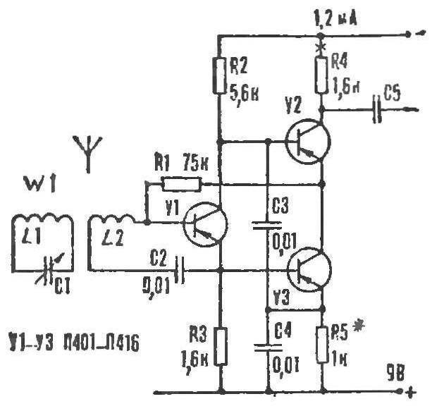
Fig. 11. Diagram of UHF to the receiver with low voltage.
 
Establishing device is to install with a resistor R12 of the current output stage of NCH within 3 mA; the voltage at the midpoint of the output stage equal to half the EMF of the battery, select the resistor R11; a change in the value of the resistor R5, the collector current of transistor V2 is doing is equal to 1 mA.
 
If the amplifier high frequency radio to improve, adding another cascade, the requirements for the selection of high-frequency transistors in this case are less rigid (Fig. 11). Emitter-follower V2 improves the performance of the amplifier as a whole and allows the use of transistors with low gain. UHF is operable even if all of the semiconductor triode will have = 10. Moreover, the transistor with the lowest gain should be used as VЗ and greatest — V2.
 
The amplifier requires little or no networking. If necessary, the collector current of V3 is set by selection of resistor R7.
 
In radio you can apply capacitors KLS, K10-7, KDK, K10-23; electrolytic K50-3, K50-6, K50-12, K50-16; diode D9 with any alphabetic index. For magnetic antennas need territoay rod length of 100-120 mm, brand with permeability of 400— 600 HH.
 
Coil L1 has 180-200 turns of wire of PEL or PEV of 0,1—0,13, L2—7—12 turns of the same wire Ø 0,12—0,18 mm. coil Winding — single layer, turn to turn, in paper frames.
 
To configure the radios only need with “fresh” battery. This will ensure the proper setting of the operating mode of the transistors. In the process of establishing the connection coil L2 with the ferrite rod removed.
 
V. MALESHEVSKI

Recommend to read

  • HEAT-RESISTANT PUTTYHEAT-RESISTANT PUTTY
    Remember, we have the oven built of red brick, there was a crack. When you are kindling from it stretched a thin trickle of bluish smoke. My grandfather made a special putty and filled...
  • INTELLECTUAL SAU “MSTA-S”INTELLECTUAL SAU “MSTA-S”
    Changed by the early 1980s, the concept of action of artillery on the battlefield demanded not only "increase its power, range, maneuverability." The foundations were laid for integrated...