
 Many years used the intercom system with loud-speaking simplex communication, consisting of a main panel and linear unit connected between a two-wire line. The radio was mounted low frequency amplifier. Here was the power source.
Each instrument is positioned electrodynamic head, performing a dual role: to convey the message it was a microphone, and the reception — worked for its intended purpose. The conversation subscribers was conducted alternately: everyone pressed the button before transmission and released at its end to receive the message.
These manipulations with the button on the remote and line unit complicates the use of the intercom system. To simplify the design, I was introduced to the scheme the volume control. Therefore, in order to avoid significant distortion to speak followed quietly, at a distance of approximately 0.8 m from the speaker, which, of course, was not always respected.
Over time, there is a need for a new negotiating unit to multiple subscribers, devoid of the shortcomings of the previous, in addition able to perform as an electronic watchman.
To solve this problem it was possible in two ways. The first is the easiest: buy any device, but the price of “bite”. Therefore, we chose the second method is to assemble it from the available electronic components and materials. Just want to emphasize that the production of this electronic device even the homebrew that is better own a hammer than a soldering iron.
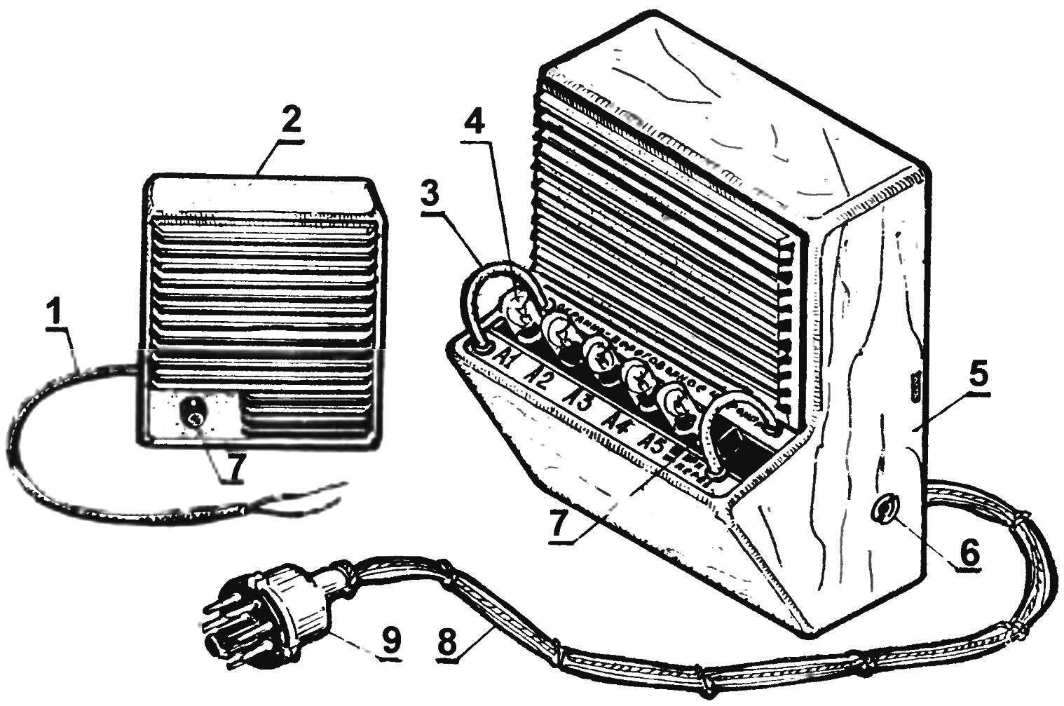
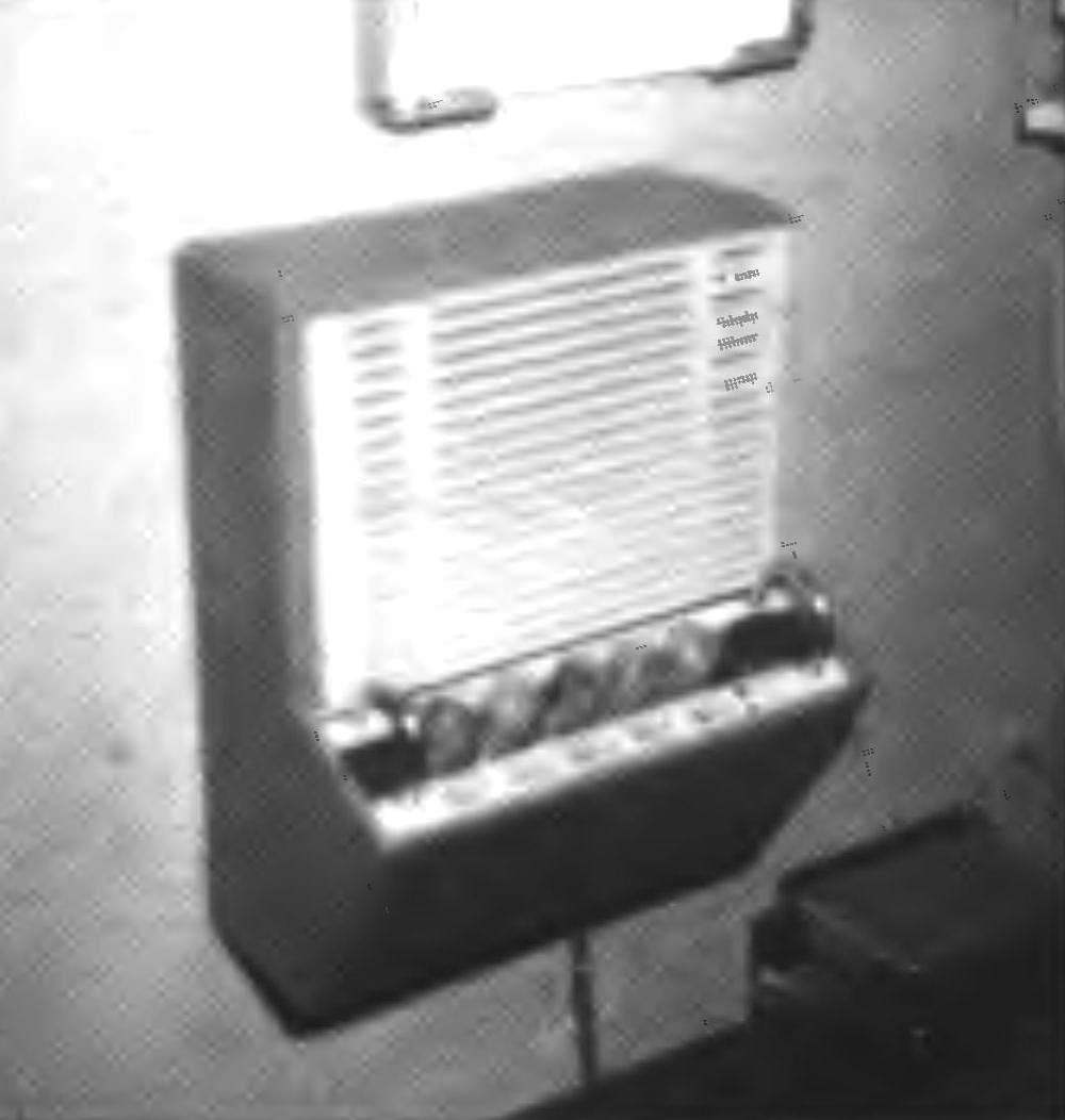
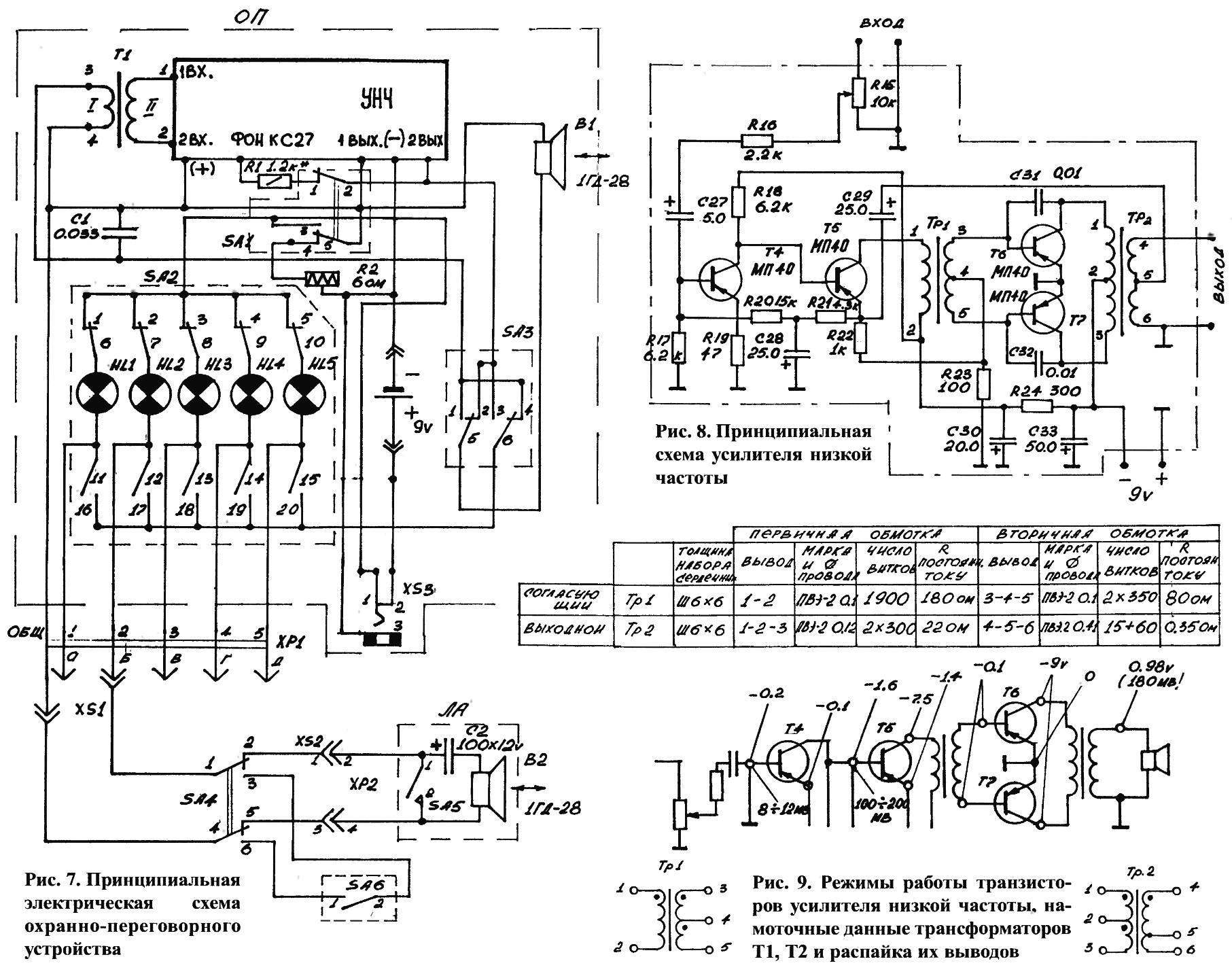
Fig. 1. Security-intercom — basic unit (OP) and the linear unit (LA):
1 — cable output LA; 2 — linear device; 3 — a safety clip; 4 — button switch LA (5 PCs); 5 — the case of the main panel; 6 — plug socket for connecting an external power source — 9 V; 7 — button switch “reception-transmission”; 8 — tow the line wires; 9 — multi-pin plug
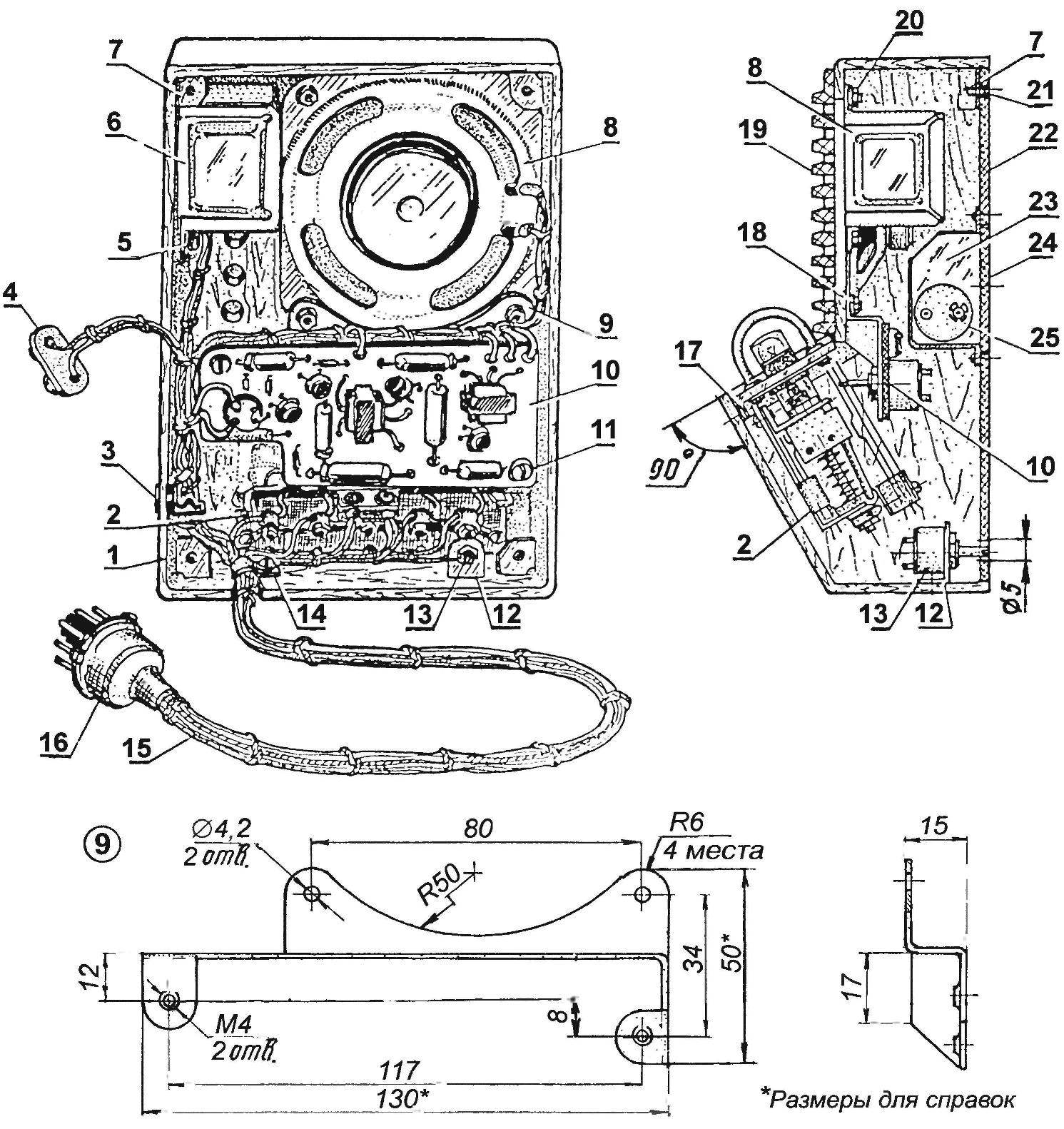
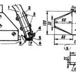
Fig. 2. Layout main panel (a rear view of the cover not shown; b — side view):
1 — body; 2 — button switch linear devices; 3 — plug socket for connecting external power supply; 4 — two-wire connector stand-alone power source; 5 — a nut of fastening of a matching transformer; 6 — matching transformer T1; 7 — shelf fastening of a cover; 8 — dynamic head 1ГД-28; 9 — bracket fastening the Board ULF; 10 — charge ULF; 11 — the screw M4 fixing Board ULF (2); 12 — bracket; 13 — variable resistor R2; 14 — clip; 15 — wiring the line wires; 16 — multi-pin plug; 17 — a regiment of push-button switch (tree); 18,20— joint nut M4 fixing of the loudspeaker and bracket Board ULF; 19 — Samandarova grill; 21 — M3 screw mounting housing cover; 22 — back wall of the case; 23 — battery compartment; 24 — battery cover; 25 — battery
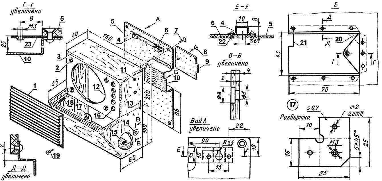
Fig. 3. The case of the main console:
1 — decorative and protective grille (plastic ventilation grille); 2 — hole Ø4 bolt of fastening of a loudspeaker (4 PCs); 3 — housing (plywood s4); 4 protection bracket (St3, strip 15×0,7, 2); 5 — housing cover 200x151x2 (Micarta); 6 — reinforcement plate (St3, strip 15×0,7); 7 — M3 screw mounting housing cover (4 PCs); 8 — M3 screw securing the cover of the battery compartment; 9 — cover the battery compartment 70x43x2 (Micarta); 10 — compartment power enclosure (St3, sheet s0,7); 11 — hole Ø4 bolt fastening matching transformer (2); 12 — hole Ø90 under the speaker; 13 — cut under the ledge of the lid of the battery compartment; 14 — hole plug socket; 15 — cutout harness line wires; 16 — acoustic holes Ø10 (5 PCs); 17 — shelf mounting of the housing cover (St3, sheet s1, 4 PCs.); 18 shelf installation push-button switch SA2 (wooden strip, 3 PCs.); 19 — the screw of fastening of protective and decorative grille (4 PCs); 20 — the cutout under the driver magnet; 21 — cutout mounting matching transformer; 22 — rivet Ø2 (aluminum, 14 PCs.); 23 — mount plate on the battery compartment
To describe security intercom (OPU) in General, it consists of a main panel (OP) and the five subscriber line equipment (LA) that perform the functions of security sensors.
Getting started designing a new instrument, analyzed a number of suitable schematic diagrams of communication devices.
The basis of the chosen scheme, published in the journal “modelist-Konstruktor” No. 10 of 1969 author K. Samalikova. But to me, it’s not all arranged. Therefore, in the device main remote control has introduced a homemade push button switch SA2, which acts as a switch or selector. This allowed a single tap on a button to choose a line and contact subscriber that has simplified the operation of the OPU. There is no need of use by subscribers of additional switches in linear units.
But in the manufacture of GTC I even a simple amplifier circuit low frequency (ULF) has not been able to repeat due to the lack of necessary electronic components. Had to be resuscitated, and then to tailor the ULF from an old portable transistor receiver “Giala”. Structurally, the ULF is executed on a separate circuit Board on the transformer diagram. The output power of 150 mW was more than enough for confident communication distance up to 2 km. Further connected to the input of ULF matching transformer T1 is enabled the caller on the line without straining your voice, at a distance of 4 m from the linear system (LA) to carry on a conversation with the operator OP. In addition, the exception from LA button of transfer and acceptance to a limit have simplified the use of them. Although LA and there was one button, but it is now used only for a call OP.
For the protection of the object LA is still complemented by a toggle switch (installed in a hidden place), which allows you to connect to the line sensor alarm (HB). The sensor can be made independently or to apply for this purpose, reed switches, toggle switches, buttons, etc. that work on contact closure. Great sensors out of door switches for refrigerators — they I have used. The number of sensors in the protected area can reach ten. All of them are connected in parallel.
In the income statement, there is another possibility to control the protected object, a long — term audition. Doing this allows excellent sensitivity of the device. For long use, to save power plug included in the plug socket XS3 (Fig.7) and the GTC automatically switches to the power from the external source, as the latter can use a high capacity battery or mains power supply -220/-9 300 mA — I have it and used.
Security-intercom — basic unit and linear apparatuses that are mounted in the housings, assembled from plywood, nails and glue. The dimensions and shape of the housing OP is dictated by the size of the used parts: switch SA2, the dynamic head B1, a matching transformer T1, circuit Board ULF and the volume of the compartment the batteries. Case treated carefully sanded, puttied, primed, painted spray of nitro, and finally, their surface polished.
Part of the front wall of the housing OP forms a plastic decorative and protective the grille behind her is a dynamic speaker.
The front sloping panel of speakers put the switch SA2 is located on it with control buttons and safety straps-handles.
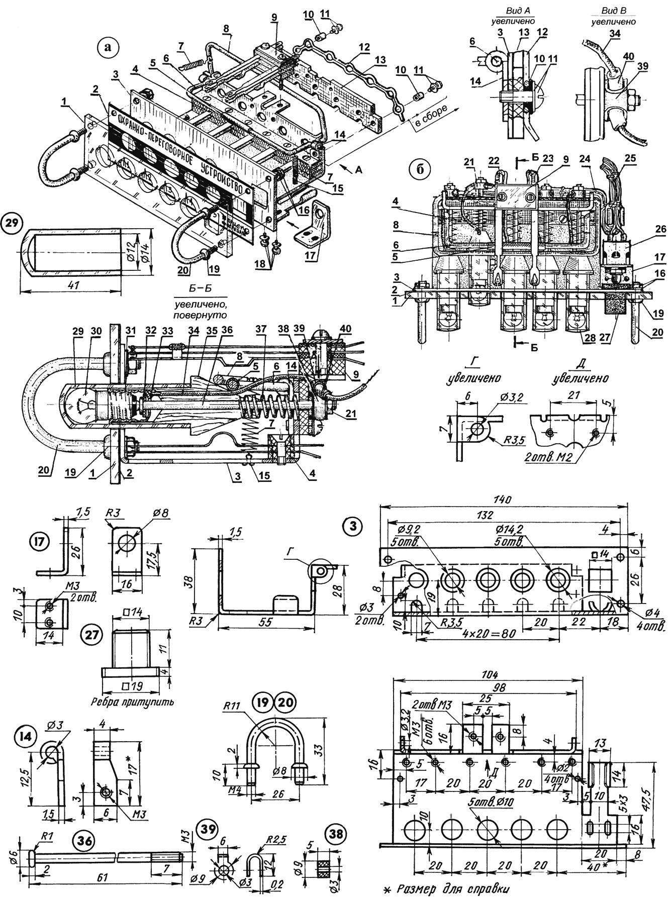
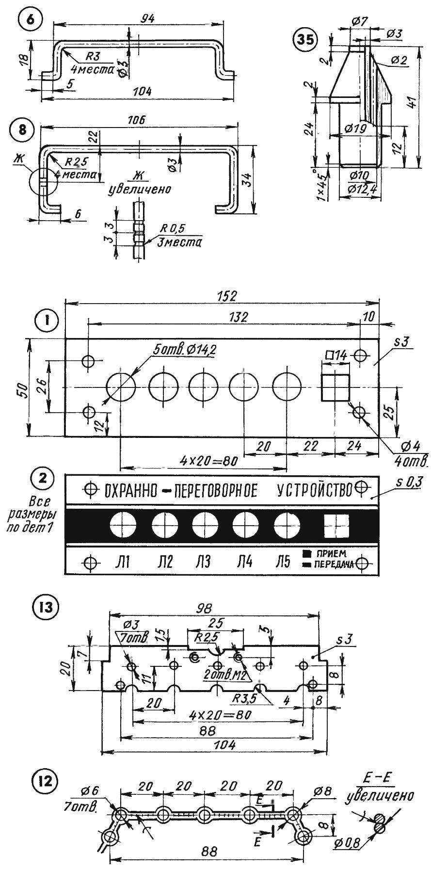
Fig. 4. Push button switch (a — unassembled, buttons are not shown; b — assembled):
1 — bezel (plexiglass, s3); 2 — dashboard (drawing paper); 3 — chassis (CT3, sheet s1,5): 4 – block the contact group of the switch SA2; 5 — insulating tube (polyvinyl chloride); 6 — bracket switch SA1 (wire Ø3, OBC); 7 — spring (normally compressed, 2); 8 — clip-retainer (wire Ø3, OBC); 9 — contact block of the switch SA1; 10 insulating sleeve (PVC, 2 PCs); 11 — M3 screw with washer (2 PCs); 12 — bus terminal 1 — 5 switch SA2 (copper wire Ø0,8); 13 — insulation panel (PCB s3); 14 — hinge brackets of the switch SA1 (St3, sheet s1,5, 2); 15 — earring (steel wire Ø1, 2); 16 — nut M4 and washer mounting bracket-handle; 17 — bracket for switch mounting SA3 (St3, sheet s1,5); 18 — M3 screw with washer mounting bracket; 19 — shaped nut M4 (4 PCs); 20 — protective bracket-handle (steel wire Ø4, 2 PCs); 21 — adjusting nut M3 with washer (5 PCs); 22 — conclusions contacts 3 — 4 — 5 switch SA1; 23 — conclusions contacts 1 — 2 of switch SA1; 24 — harness installation; 25 — tow the line wires; 26 — switch SA3; 27 — button switch SA3 (plastic); 28 — subscription-button lamp (5 PCs); 29 — a transparent cap (disposable medical syringe); 30 — bulb MH-6.3; 31 — electroputere; 32 — insulating washer; 33 — a brazed contact of the cap and a flexible wire; 34, a flexible wire (from the brush of the vacuum cleaner in isolation); 35 — the shell buttons (black); 36 — rod (brass); 37 — return spring; 38 — an insulating bushing (rubber); 39 — brace (brass, sheet s0,2, 5 PCs); 40 insulating sleeve (PVC, 5 PCs); 41 — insulating plank (PCB)
In the right wall of the housing mounted socket HS connect an external power source.
A removable back wall OP fastened with M3 screws to the shelves; it, in turn, docked by the Bay for stand-alone power source (Fig.Z). Cover fastened with screws.
Working position the OPU may be horizontal (on the table), but easier to place it vertically (on the wall). For hanging in the lid of the case there are loops with protective straps, to shield against accidental damage to the electrical installation.
For cases of LA you can use any boxes, the dimensions of which will allow you to place them in the dynamic driver and the call button. In case you need to hide LA from dashing people need to “disguise” under the discreet clothes, toys, etc.
To ensure a reliable and durable work of all parts of the income statement, you need to properly connectors detached from the house construction it is desirable to hold the so-called “fieldwork” — the wire, which along with the copper conductors is steel, making it strong and tear. The insulation of this wire withstands atmospheric and mechanical influences, and the dark color makes it almost invisible, which plays an important role in the use of “fieldwork” in the lines of a hidden alarm. Fit, of course, and another wire, but, as they say, will be more of a hassle.
The most sophisticated in the OP is a push button switch SA2. Although the wiring diagram of its mechanical link with the SA1 will not be shown, in fact, pressing the select button line subscriber switches occur simultaneously. Clear operation push-button switch depends on the quality of its production, the adjustment of the gap between the contacts, as well as the material from which they are made. I used the contact springs from the relay DC is RPN-70, which is made of a special alloy of Nickel silver with a diameter of 0.5 mm.
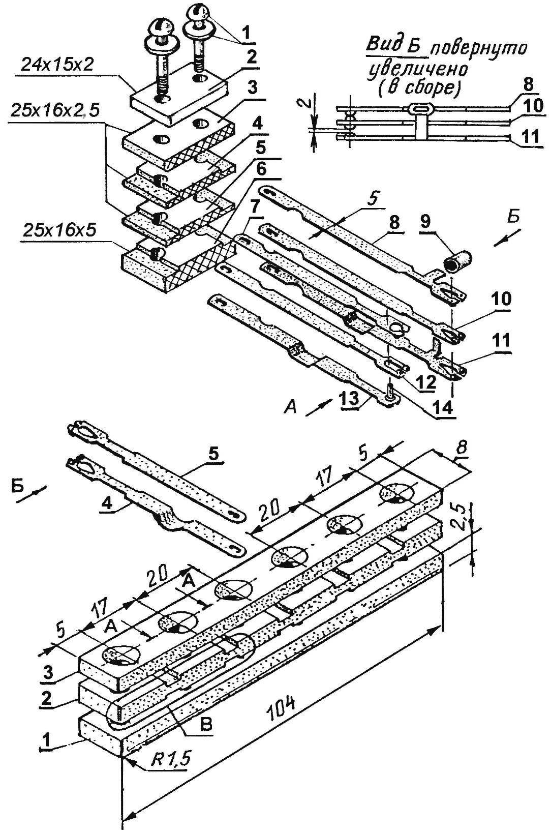
Fig. 5. Contact block SA1:
1 — M3 screw with washer (2 PCs); 2 — clamping strip (St3, sheet s2); 3,4,5,6 — insulating plate (Micarta); 7,8,10,11, 12,13 — spring pins (brass); 9 — insulating tube (PVC); 14 —boss (plastic or other solid insulating material)
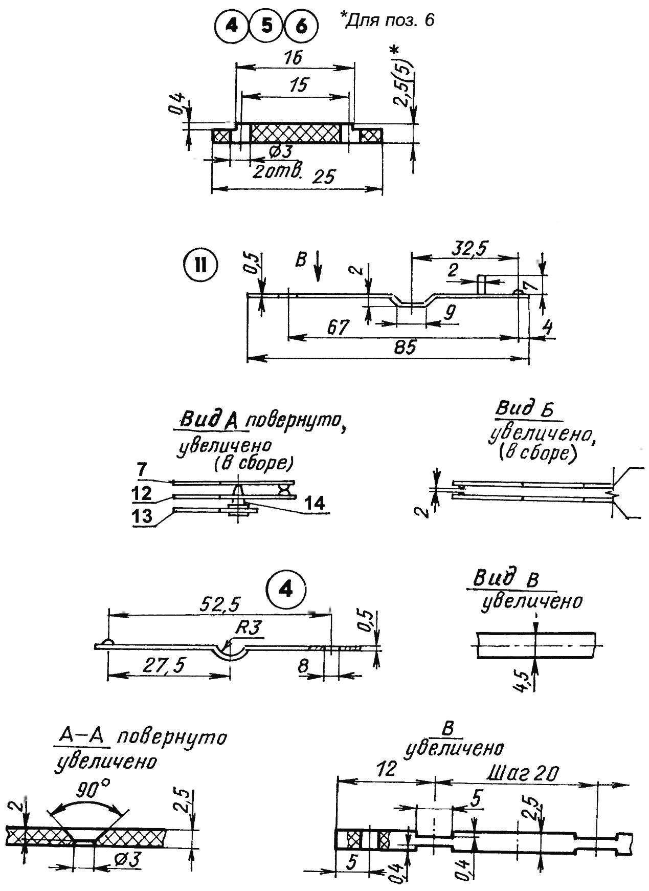
Fig. 6. The contact group SA2 11 – 20:
1,2,3 — insulation plate (PCB); a 4.5 spring pins (brass)
The attached figure 4, the switch SA2 should clarify. Transparent caps are made of pieces of disposable medical syringes with capacity 5 ml. of Electrical cartridges — from garlands. The button turned on a lathe from the butt portion of well-dried birch. To improve the insulating properties and resistance to atmospheric moisture of the body is impregnated with bakelite varnish. The Central insights of light bulbs made from strips of flexible wires from the brushes of the generator enclosed in a thin-walled elastic insulation.
Wall mounting electric wire OP — in the form of bundles, tied with synthetic thread soldered to the plug pins (from old radio). The latter is connected to the socket on the panel to which soldered wires connecting the lines of subscribers. Matching transformer (-220 V/-9 V) shielded from the power supply of a portable tape recorder, used without alteration. Its primary winding in the device plays the role of secondary and secondary — primary. Dynamic head 1ГД-28 (B1, B2 — B5) can be replaced with power from 0.5 to 2 watts. (This may deteriorate the frequency response and decrease the communication range.)
Now more about the work of the security communication device. Guided by the scheme depicted in figure 7, an example of communication with the caller No. 2.
Calling number 2 line machine operator from the main console
Tap turns on the second switch SA2, which creates a food chain ULF the chain: plus, HS 1 — 2, SA1 3 — 5, diagram of the ULF, minus.
Clicking AS (sending and receiving) to the input of ULF connects the chain B1: B1, AS 1 — 5, T1 3 to 4, V1.
Thus, Q1 acts as a microphone.
At the same time to the output of the ULF in the chain..1 ULF, “common” line cord, 4 SA4 — 5, 3 XS2 — 4, the winding B2, XS2 1 -2, 1 -2 SA4, line conductor B, SA2 12 — 17, AS 3 — 6, out.2 ULF — connects B2 LA callee. After the conversation the operator OP (not a strong tap on any of the remaining buttons is not enabled) disables the subscriber from the LA No. 2. In SA2 12 — 17 contacts are opened, and the SA2 2 — 7 are closed, creating a circuit for the operator OP.
The call to the subscriber No. 2 LA of the operator OP
Briefly pressing the button SA5 subscriber No. 2 LA creates a food chain ULF OP: plus, HS 1 — 2, SA2 2 — 7, HL2, linear wire B 1 SA4 — 2, XS2 1 — 2, 1 SA5 — 2, 4 XS2 — 5, linear wire “Ls.”, ULF, minus.
As ULF covered by positive feedback through the chain..2 ULF, 1 SA1 — 2, R1, С27 ULF, he is excited and in B1 OP will create oscillations of audio frequency. The tone of the sound, thus, is selected by changing R1.
In addition to a call signal lights bulb HL2 mounted in the button and the operator OP visually checks the caller’s number LA. Instead of HL1 — HL5 is possible to establish so called writ of the valve with an opening door, behind which is the subscriber number.
After receiving the call signal, the operator OP by pressing the appropriate button SA2 is connected to the calling LA. Clicking IS, the operator OP has a conversation with the contact No. 2 of LA. After the conversation, the light touch on not included any button on the panel SA2, the operator brings the device to its original position.
In conclusion, complement the explanation of the work of the GTC in the role of a watchdog device. Upon receipt of a signal from the protected object switch is implemented by inclusion in the plug socket HS unused two wire plug that breaks the supply circuit of the ULF. Removed plug from socket, once established and eliminated the cause for the alarm.
V. PETROV, S. fish, Krasnoyarsk Krai
Recommend to read
 GENTLE TRUNK
There are many clamps to secure the roof rack of the car. However, quite comfortable and no unsightly gutters on the roof I did not have to meet. Offer readers the "M-K" I developed... Compact gearbox for a low-pressure tire vehicle
Low-pressure, large-diameter pneumatic tires are excellent propulsion systems for all-terrain vehicles even in the most difficult road conditions. However, when they work with modern...
