
 The device is assembled on the proposed scheme allows to control the power consumed from the DC voltage source. Indication power led is a color display and sound. When using in-vehicle device control the power consumption of lighting devices and additional equipment replaces the voltmeter, connected in parallel with the battery.
The maximum value of the monitored current in the load circuit 10A. The diagram represents essentially an ammeter that uses an led indicator green — low consumption current, a red glow — when a critical current consumption Red led is duplicated by a sound signal — background in the primer B1 (if applicable capsule without built-in AF generator, for example, type VP-1, SN-18, dam-4A or equivalent), and indicates that the load must be switched off immediately. When used as B1 capsules with integrated generator, AF sound will be loud and single tones.
A distinctive feature of the device is that it provides for the adjustment (setting) of the control at all three levels (variable resistors (R4, R7) Elements are mounted in a compact enclosure the Device does not contain scarce details and can be used standalone, portable and is very useful for vehicles with a voltage of 12V Device does not require configuration, except for setting the thresholds is stable and reliable To connection diagram with external controlled systems provides a connector (e.g., RP-10-11). Adjustment is multi-turn variable resistors of the type SP5-1ВБ with linear characteristic according to the following criteria. the current in the load circuit is below 2 And is considered to be low, 2 — 4 A — average, more than 4 And high If these threshold levels to follow in the Autonomous operation mode with low current consumption (green led), then power the load devices from a standard battery with capacity of 55 — 60 A/h duration of discharge will be approximately 20 hours.
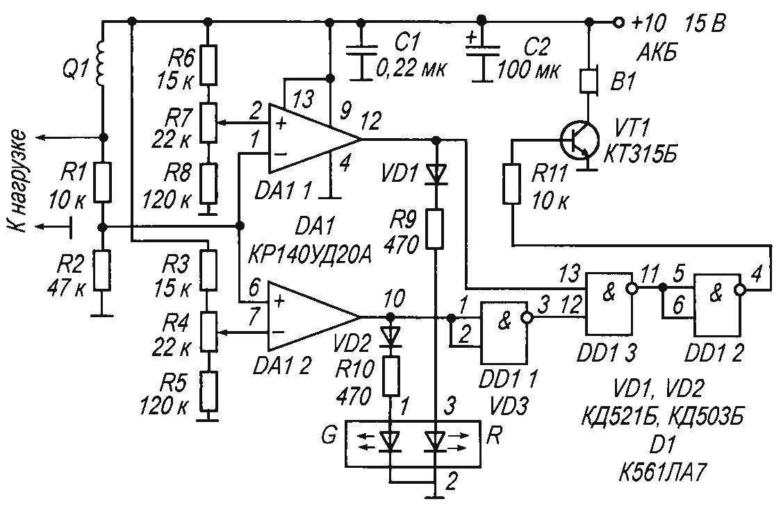
Fundamental elektricheska diagram of the power control
If the sound is not necessary, the chip D1 K561LA7 with elements obleski rule.
Details
As B1 use any sound generator, e.g., piezoelectric capsule with a built-in AF generator type KR1-4332-12 current Amplifier implemented by transistor VT1, and controls the operation of the sound generator Transistor using silicon n-p-n conductivity low and medium power, for example, КТ312, KT315, КТ3102, КТ503, КТ601, КТ603, КТ605, КТ608, КТ630, КТ940 with any alphabetic index.
Q1 — cut stranded insulated wire, cross-section of 1 mm and a length of 60 cm fixed resistors type MLT-0,25, Mr-25 or similar non-polar capacitors — type KM-6 Led — type АЛС331АМ, АЛС331БМ, КИПД18В-M, L-239EGW or similar Capacitors C1, C2 filter noise on the power C2 — electrolytic capacitor type K50-24, designed for a working voltage of not less than 16 or similar Diodes VD1, VD2 type KD521, KD522, Д310, Д220, Д311 with any alphabetic index
The practical application of this device is not only in car but also at home, in different devices working laboratory Amateur radio operator, saving energy and signaling the exceeding of consumption current from the load devices.
Recommend to read
 AND A SHOWER AND WARDROBE
Almost every cottager is trying to equip on the site the shower: it's nice in the summer heat PLI after active physical labor to feel the soothing coolness of the water jets. But... PROGRAMMABLE CODE
In technical literature there are many publications on improvised electronic code locks — variety of complexity and management that is performed on chips as small and medium scale...
