
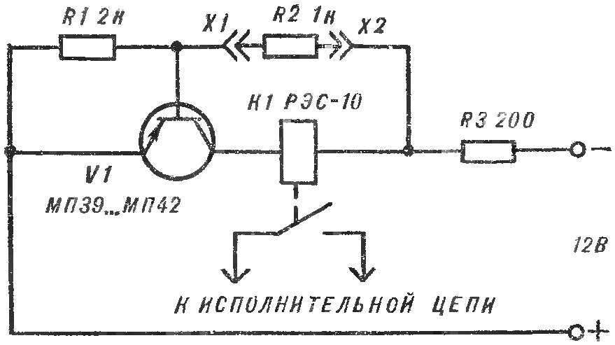
 In the fourth issue of the journal for the year 1978, published schemes of electric locks with a “secret”. They all work well, but they, in my opinion, there is one drawback: the locks can not be powered from a DC source. I propose a scheme for electronic lock, the key to which is the resistor. Here’s how it works. When the terminals X1 and x2 (see diagram) connect the resistor R2, transistor V1, the base voltage goes negative, opens and relay K1 is triggered.
If X1 and X2 are short-circuited to the base of V1 goes negative the potential, but relay K1 remains de-energized: the coil shunts jumper and a low impedance transition “emitter — base” of the transistor.
The RZ resistor limits the current consumed by the device, and through resistor R1 to the base of the transistor is fed a positive bias.
In the schema lock is applied, the relay RES-10 (RS4 passport.524.302). Spring anchor he need to bend.
In the closed state of the lock consumes a current of about 6 µa when the opening — about 30 mA. The device starts to work immediately after Assembly. Moreover, the resistor values may differ from those listed on the diagram.
G. AROVET, S. Antonivtsi, Khmelnytsky region.
Recommend to read
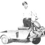 ALL-TERRAIN VEHICLE OF JUNKS
"For ten years this versatile motorcycle is my indispensable assistant, shares with us A. Belyaev from the village of dzhonka Khabarovsk region. In winter the rear wheel I replaced the...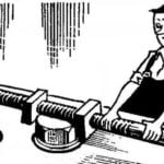 UNSCREW THE SCREW…
When you do not have a suitable spanner to Unscrew the hex-head bolt will help out any screw with two nuts — preferably square-shaped.
