
 Security systems are a rapidly developing area of modern electronics. Published a huge number of various schemes and designs that can make anyone a couple of times was holding the soldering iron. For example, “electronic security guards” can warn of an intruder enters the premises or to signal the presence of the recorder for unauthorized sound recordings.
It often happens that one only blinking LEDs and alarms buzzers accompanying electronics may scare off the intruder.
To make such devices easier. Using small reed switches, even a novice radio Amateur able to solder a whole set of instruments, the “electronic guard”. On several examples, we describe what should be a diagram of each instrument, the technology of the manufacture of such devices and even how to control the work of security electronics, using Internet technologies.
Reed switches accepted abbreviated name sealed contacts. In fact, it is the same relay, but without an anchor and mechanical connection with the contacts. Contacts gerco-enclosed in a sealed enclosure and closed when subjected to a magnetic field (e.g. permanent magnet). Commercially available reed switches with different sizes and performance characteristics, which are divided into three main types: reed switches-circuit switching and disconnection. The following schemes are used, only the reed switches circuit having a normally odomknutie contacts.
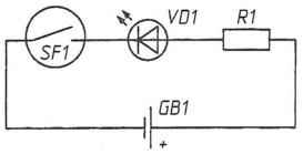 Consider the simplest scheme of magnetic field indicator, which can be used to detect tape recorders, having a small speaker (Fig. 1). The operation of the device is very simple – in the case of approximation of the indicator to the recorder, the dynamics of the magnet closes the contacts of the reed switch SF1 and illuminate the alarm led. To produce this indicator it is possible to take the led VD1 with a supply voltage of 3 V and the GB1 battery-type CR2025 or CR2032 also at 3 V. the resistor R1 can be excluded from the scheme. In the case of higher voltage the resistor will be required, and its value is easily calculated from Ohm’s law for subcircuit. The indicator can be used in any small reed switches.
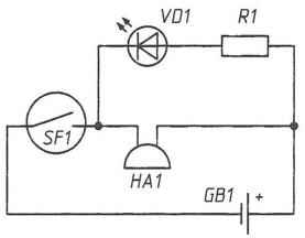 You can make this device more “solid” if you add just one element – buzzer HA1 3 Q. turning parallel to the led, the buzzer (Fig. 2), we obtain the magnetic field indicator, when activated the led should be illuminated, but buzzer will sound.
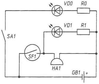
Before using the indicator it is useful to verify the batteries. Change the scheme again, by connecting the led VD0 and SPST switch ЅА1 as shown in Fig. 3. In this case, when the closure of the contacts of the switch will always be led VD0, signalling about the health of the power supply.
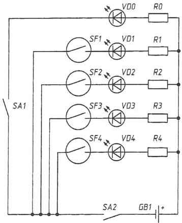
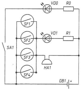
Reliable to see such a device? Yes, if you bring the reed switch close enough to the speaker (the voice recorder speaker). Unfortunately, the contacts of the reed switch may not be closed in that case, if it is set at an angle. Much more reliable will the device, whose scheme is shown in Fig. 4. Here four parallel reed relay SF1-SF4, which initially can be set at different angles to the magnetic field source. Thus, the probability of triggering at least one reed switch will be higher and the indicator will become more sensitive.
 Based on the same principles, you can create a simple security system to protect the premises from intruders. Its scheme is shown in Fig. 5. In this case, the reed switches installed on doors and Windows so that initially each of them is adjacent to a small magnet. For example, you can install the reed switch on the door and the adjacent magnet is nearby, on the doorframe. When the door is closed, the reed switch contacts will be closed and the led for the corresponding alarm will be lit. As soon as the intruder opens the door, the led immediately turns off indicating an open circuit.
 Interestingly, even such a simple security system can be very effective if used in combination with Internet technologies. A personal computer and a web camera will help you every second to track the immunity of the premises from any geographical point, capturing both the integrity of the doors and Windows. It is sufficient to send webcam on the panel with signalling LEDs. Greater opportunities provides the use of such computer programs as, for example, a freely distributed Easy Free Web Cam. It is alleged that through this program, the camera can be used as a security system with motion sensor. As soon as the program detects a change of image in the frame, the camera starts shooting automatically downloads the image to the specified server, and to top it destroys the attacker in horror, issuing through the speakers of a dog barking. In the program you can customize the accuracy of determination of moving objects in the frame.
 Generally, if you show flexibility of mind to come up with many interesting security schemes using reed switches. In particular, it is possible to make a combination lock that is triggered when a specific location of the reed switch and closing the contacts, magnets, and much more. Will briefly focus on how to make simple printed circuit Board for such structures. As a rule, the use of printed circuit boards allows to reduce the size of electronic devices and increase the reliability of their work. In printed wiring connection between the parts by using a thin flat conductors applied (as if “printed”) to the Board.
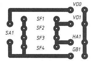 The blank for the printed circuit Board is usually a phenolic paper or a glass fiber glued on a thin copper foil. On the surface of the foil applied with lacquer (nail Polish) a printed circuit Board pattern. Once dry, paint the lower cost for etching in ferric chloride solution. Periodically shaking the container with a Board, provide it with a uniform wash solution. In the process of etching the portions of the foil under a layer of varnish are intact, whereas in other places the copper foil is removed (etched). Next you need to flush the charge with running water, dry them and remove the Polish with a swab and solvent. On the surface of the Board will be drawing from thin copper conductors. In places the future installation details drilled hole with a diameter of 0.8 – 1.5 mm. View the PCB for the indicator of the magnetic field on four reed switches are shown in natural size in Fig. 6. Preferably after the soldering of details all the joints to cover a colored transparent varnish or purpose varnish. On the one hand, this protects the solder from the effects of the environment (adverse weather, climatic conditions), and on the other hand gives the circuit Board a finished look with all the attributes of industrial design.
Recommend to read
 A WAVE OF THE HAND
Not long ago, musical instruments even pop bands — be it saxophone, violin, accordion, piano, double bass and even a drum — gave his listeners a natural, "natural" sound. Today music has... “SERVING” TABLE
If you take the end-of-century baby carriage and clamped on a plywood panel with holes and shelves, you can get a very comfortable truck to embed a whole set of tools to take care of a...
