
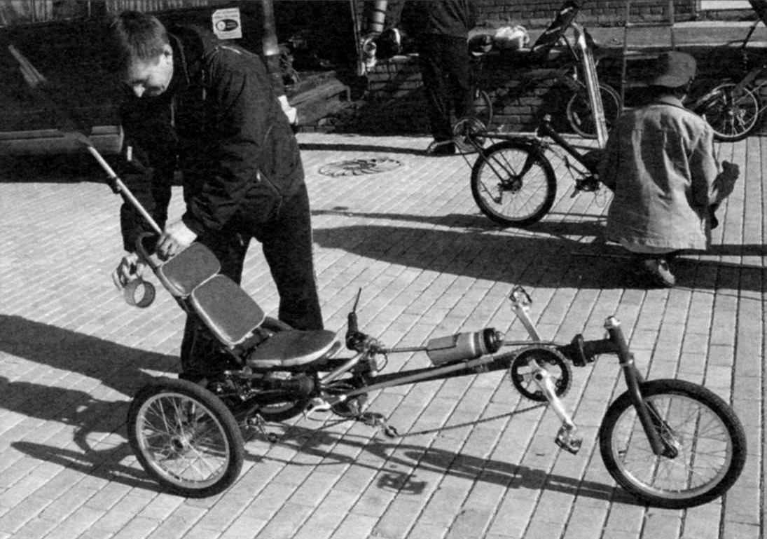
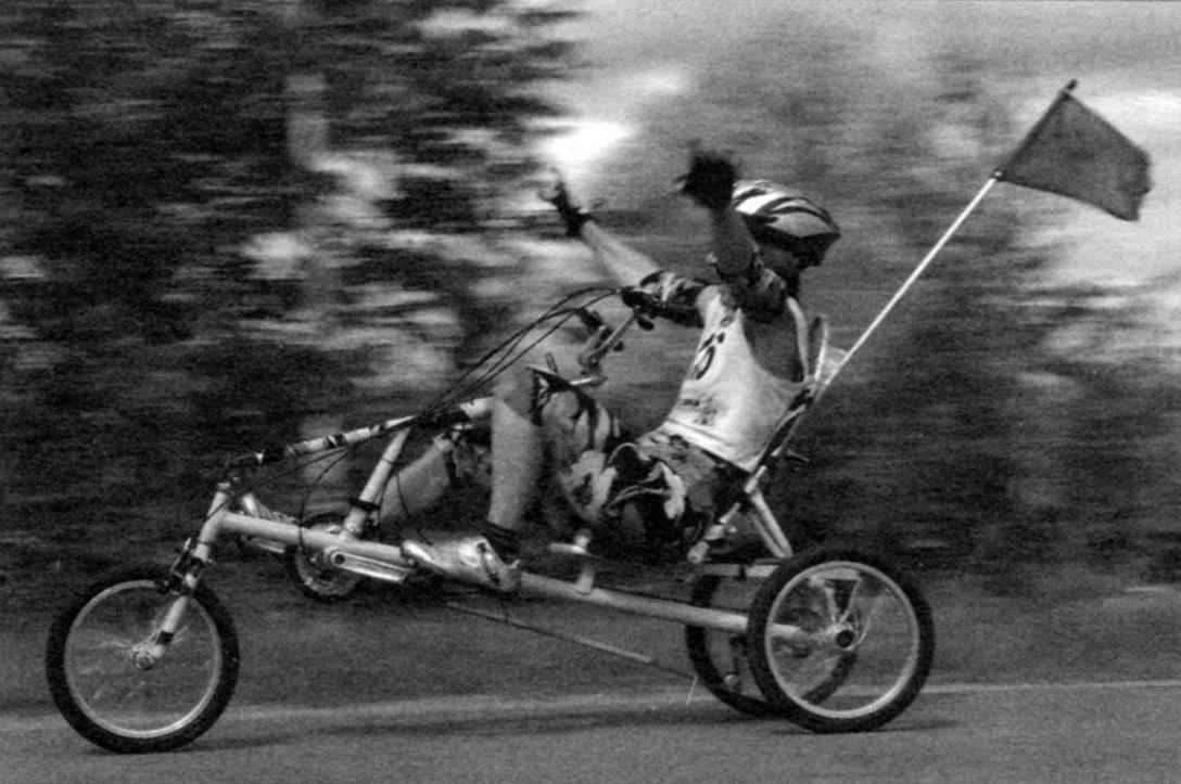
 Once the attention of mushroom pickers has attracted tourist from approaching trains in bright veloform, helmet with “cello” in the case behind. Removing the box and opening his zipper, took out of it… brilliant frame with wheels. A few motions – and before the astonished mushroom was already a three-wheeled velomobile. The box on the trunk itself – in the saddle, and in a minute a tourist in a strange car disappeared around the bend suburban road…
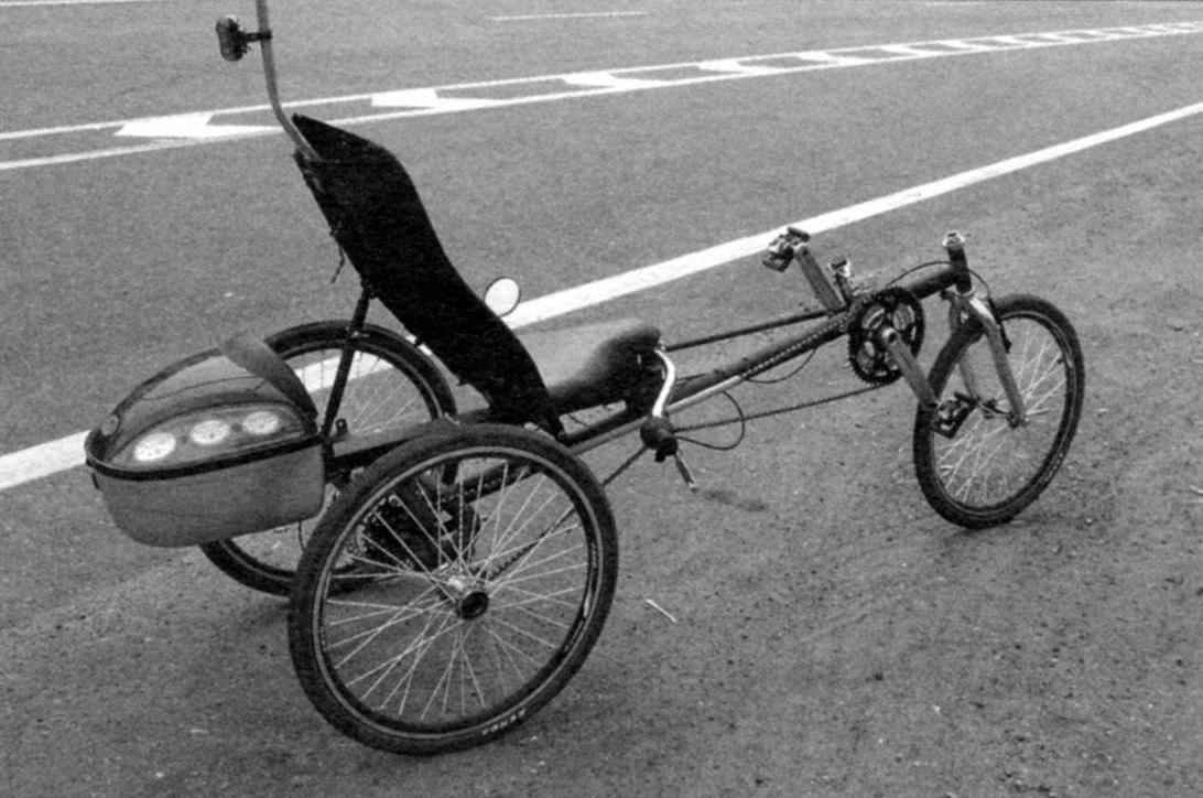
A prototype of this velomobile was the model “Catweasel”: single, tricycle with one rear wheel that I had the opportunity to try out a few years ago at the annual antique auto festival “autoexotic” in Tushino. “Catweasel” serially produces a small German firm “the Chazeh”. Simple, dynamic and stable car with a little rear camber and the wheel “avatar” I really liked it. Only, in my opinion, the lack of significant dimensions: it is inconvenient to keep in a city apartment.
There was a desire to make a velomobile same scheme, but more compact and simple. Thus was born the project “Catula” -the name he was given fellow velomobiles: “Cadvise-ulyanovskogo”.
The design of the velomobile turned out to be very simple. In the tricycle scheme with a long base (when the caret is positioned between the seat and steering column) leading only one rear right (in the direction) wheel. But that didn’t affect the ride qualities (or rather, on the road), because “Katuli” a fairly narrow track – only 546 mm. But surprisingly, recumbent and with this track proved to be resistant to lateral roll over, even despite the fact that the seat base (and, hence, the center of gravity with driver) is relatively high.
Recumbent consists of the following main units: frame; drive and transmission (the node of the carriage and the intermediate shaft, two-stage chain transmission, block sprocket, shaft-axis); the three identical wheels (front driven wheel from the fork, two rear wheels: right-hand drive left – just a reference); steering; brake; seat and trunk.
Frame – welded, made from thin-walled (1.5 mm) steel (brand stalls – St.10) pipe outer diameter from 34 to 40 mm. the Frame has a hinge joint for folding into the transport position or storage. To facilitate the frame (roughly 1 – 1.5 kg) it is possible to use pipes with a wall thickness of 1 mm, but of better quality steel (such as 30KHGSA). However, this steel increases the cost of construction, requires a higher qualification of welders and heat treatment to relieve stresses in the weld seams.
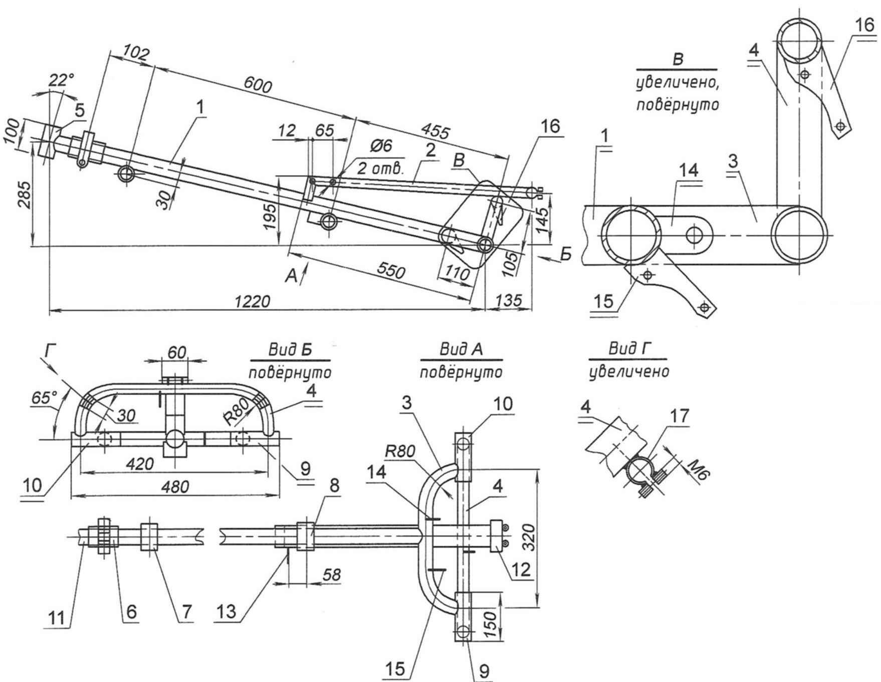
Frame:
1 – spinal longitudinal (pipe d40x1,5);
2 – seat guide rail (pipe);
3 – most (lower) arc (pipe d34x1,5);
4 – small (top) and Doug (d26x1,5);
5 – a glass of steering column (tube d34x2);
6 – hinge folding frame (third party product);
7 – body carriage (pipe d38x1,5 mm);
8 – piece intermediate shaft (pipe d35x1,5);
9 – housing axle (shaft) of the drive wheel (tube d35x1,5);
10 – the case of the half shaft (axle) wheels (pipe d35x1,5);
11 – adaptor (tube d40x1,5);
12 – terminal trunk (pipe d23x1,5);
13 – support bracket of the switch gear of the intermediate shaft (steel strip 25×4);
14 – mount adapter disc brake caliper right wheel (steel strip 25×4);
15 – bracket rear speed switch (steel strip 25×4);
16 – mount adapter disc brake caliper right wheel (steel strip 25×4);
17 – terminal wing stand wheels (2 PCs.)
Welding frame is produced in the simplest slipway, made of chipboard (MDF) with a thickness of 12-16 mm. On the stocks were drawn horizontal (top view) projection of the frame at 1:1 scale and contour with wooden bars dimensions mm 25x25x60 and screws were fixed to the spinal longitudinal tube, a continuous tube blank with a length of 480 mm housings axle and rear axle wheels, small and large arcs.
All of these elements of the frame are connected to each other by welding “tacks”. The position of the small arc that is welded perpendicular to the slipway, controlled by a square. Last prihvatyvaya guide seat, after which the blank frame is extracted from the pile and performed the final welding parts and seams.
Then on the stocks, secured the bars, the housing of the carriage, is installed on top of the blank frame they also weld. In the same sequence and is welded to the housing of the intermediate shaft.
Finishing operation – welding of the steering column Assembly. This node consists of glass adapter and hinge frame – he borrowed from folding Bicycle “Kama”. It is advisable to weld these parts together in a separate slipway and immediately treat the seams.
The steering column Assembly Assembly with front plug is attached to the bench frame with two steel angles and threaded rod – the simulator axis of the front wheel.
After you complete the work on welding of the frame, cut the middle part of the pipe billet axle housings. Thus, both formed of the housing (axle and driveshaft) rear wheels and ensures their alignment.
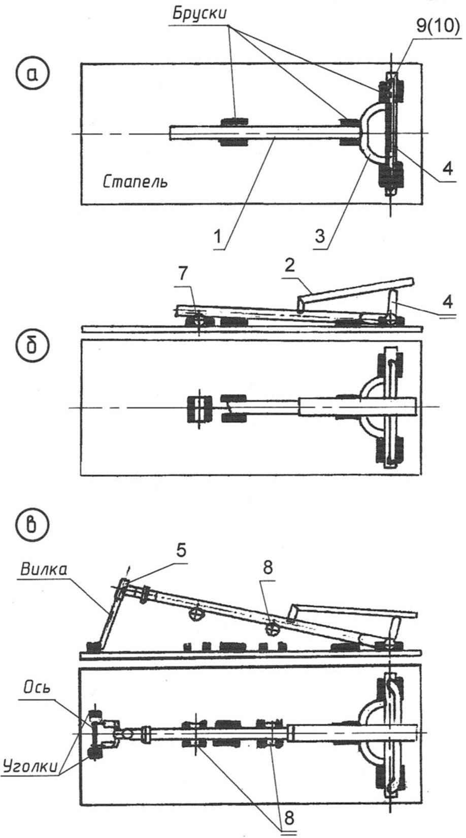
The sequence of Assembly (welding) of parts of the frame on the stocks
(the item numbers match the drawing of frame):
a) Assembly of the main part;
b) mount welded to the side rail housings of the carriage and intermediate shafts;
C) welding glass, steering column (complete with fork, front wheel and axle)
Here it is worth noting that all the shafts (carriage-and intermediate), axle shafts and axle rear wheel it is best to carve thick-walled (2.5 – 3 mm) steel pipes, to avoid deformation of seats under bearings when welding. But it is permissible to combine them from the steam pipes of a suitable diameter, as shown in the example housing axis support (left) rear wheel. For this we need to choose two of the mating pipe to the inner diameter of the outer landing was equal to the diameter of the bearing. For example, the outer tube has a size in diameter 35×1,5 mm. it made a few holes with a diameter of 8 mm. spacer (internal) pipe diameter 32×1,5 mm for forming on the entire length is made through kerf width of 2 mm, after which it is inserted inside the first and welded to it through hole “plug lap joint”. The same can be produced and the rest of the body.
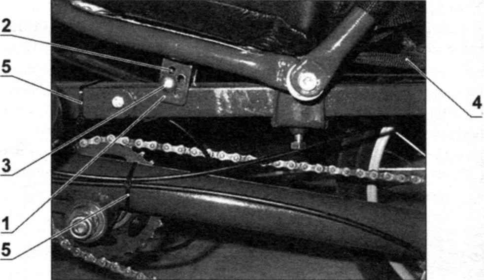
Then welded to the frame support bracket of the gear switch intermediate shaft, clamp Assembly rack mounting brackets rear shifter. Brackets adapters machines (also known as the caliper, caliper) disc brakes are welded later at the place.
The frame of this design provides adequate precision and is well suited to manufacture even small batches (5-10 pieces) of RAM velomobiles. To repeat the first operations welding rods must be removed.
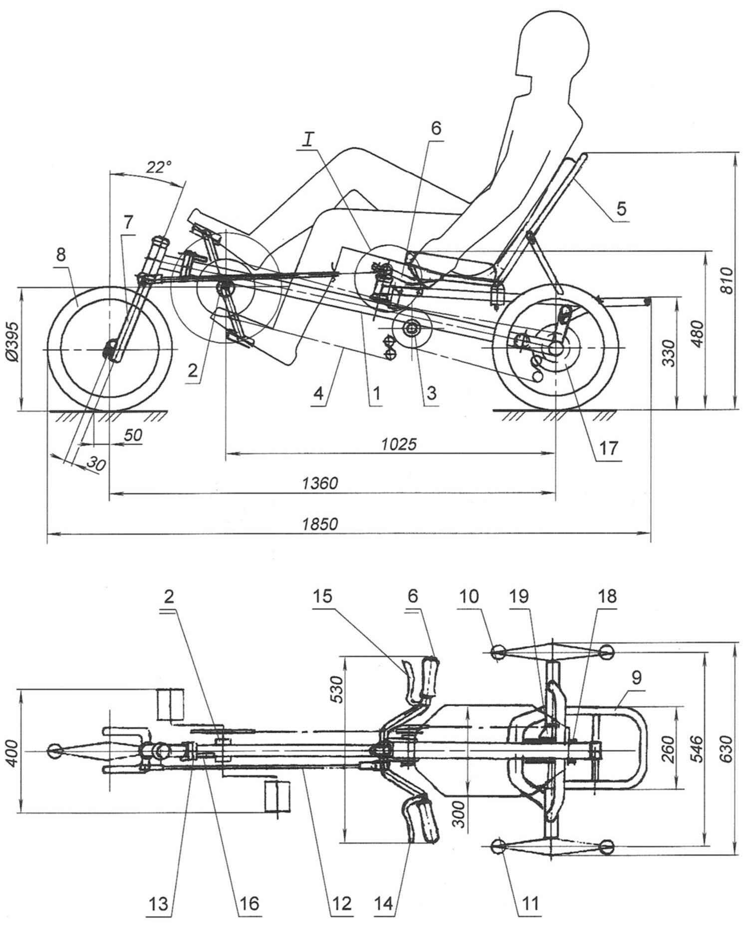
Recumbent “Catula” (seat cushion on the top view and the wings of the wheels is not shown):
1 – frame;
2 – bottom bracket with the crankset and the drive sprocket;
3 – intermediate shaft;
4 – chain drive;
5 – the seat back;
6 – steering unit;
7 – fork of the front wheel;
8 – front wheel;
9 – trunk;
10 – leading rear wheel;
11 – rear support wheel;
12 – tie-rod;
13 – hinge frame;
14 – the trigger is brakes support wheels;
15 – trigger brakes the drive wheel,
16 – latch hinge frame;
17 – brake disc of the left support wheels;
18 – brake disk right drive wheel;
19 – the block stars
Transmission. The shafts of the carriage with recesses for standard bearings are on sale. After assembling the bottom bracket the edges of the hull need to roll in several places. But there is a more preferred option: to carve the body of the carriage, cut the ends of the thread, and set a standard cartridge (the shaft of the carriage Assembly with bearings, placed in the Cup with outer thread made at its one end, and the centering Cup, screw-in the housing on the opposite side).
As the intermediate shaft and axles drive and load wheels used front wheel axle from the old moped “Riga”.
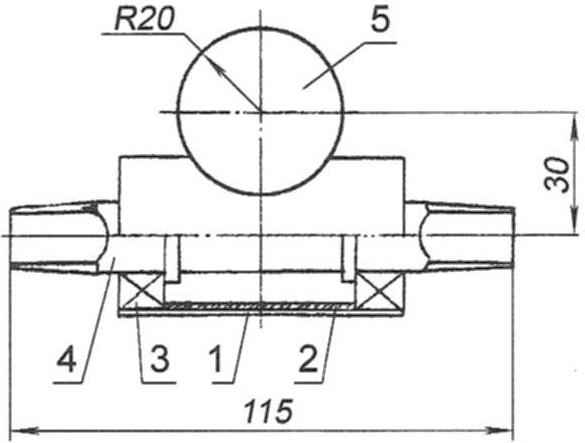
Carriage:
1 – casing (steel pipe d38х 1,5);
2 – spacer (steel pipe d35x1,5);
3 – ball closed 35x16x12 bearing (2 PCs.);
4 – shaft;
5 – spinal longeron
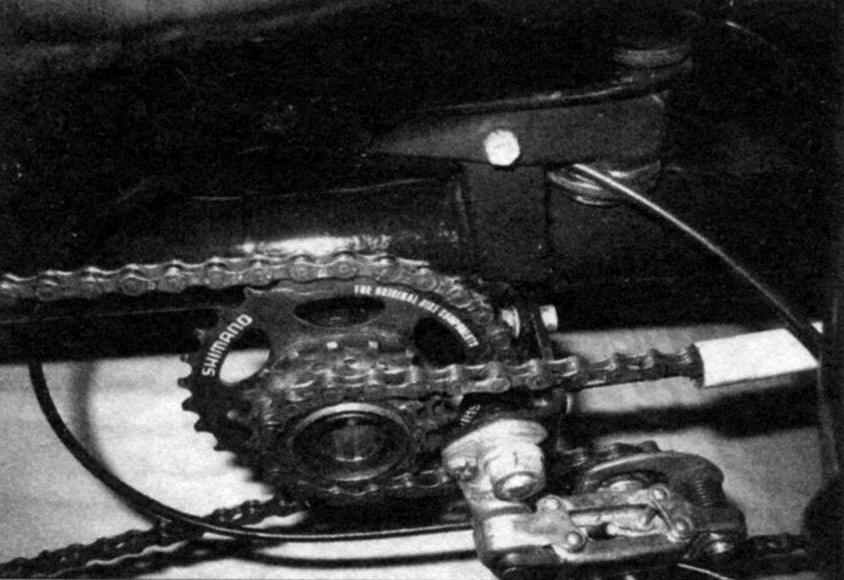
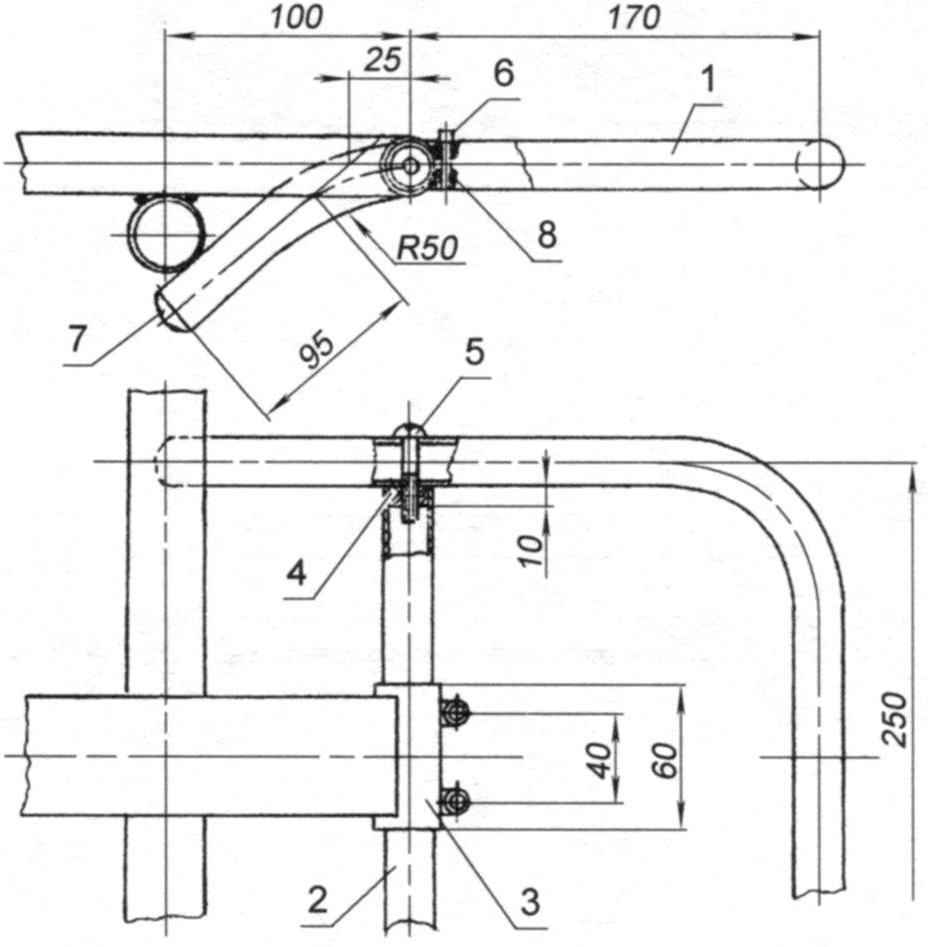
Node of the intermediate shaft. Tip to the intermediate shaft enough to weld at three points. The axis of the bolt to the gear selector could be combined with the axis of the intermediate shaft. But in the drawing he made a few forward, similar to the installation of the rear derailleur. Nuts for easy disassembly of the bracket that is welded to the support.
A standard set of asterisks (“sistemic”) were altered: removed the last two sprockets and replaced the spacer rings from the same rattles. Or you can carve spacer, providing a distance from the nearest to the star (a), which supports the circuit of the second stage drive not less than 11 mm.
The rear-wheel assemblies. Before you start talking about the nodes, it should be clear that each rear wheel is mounted on its axle shaft. But since the right drive axle and transfers the wheel torque will be referred to as its shaft and the other just axis.
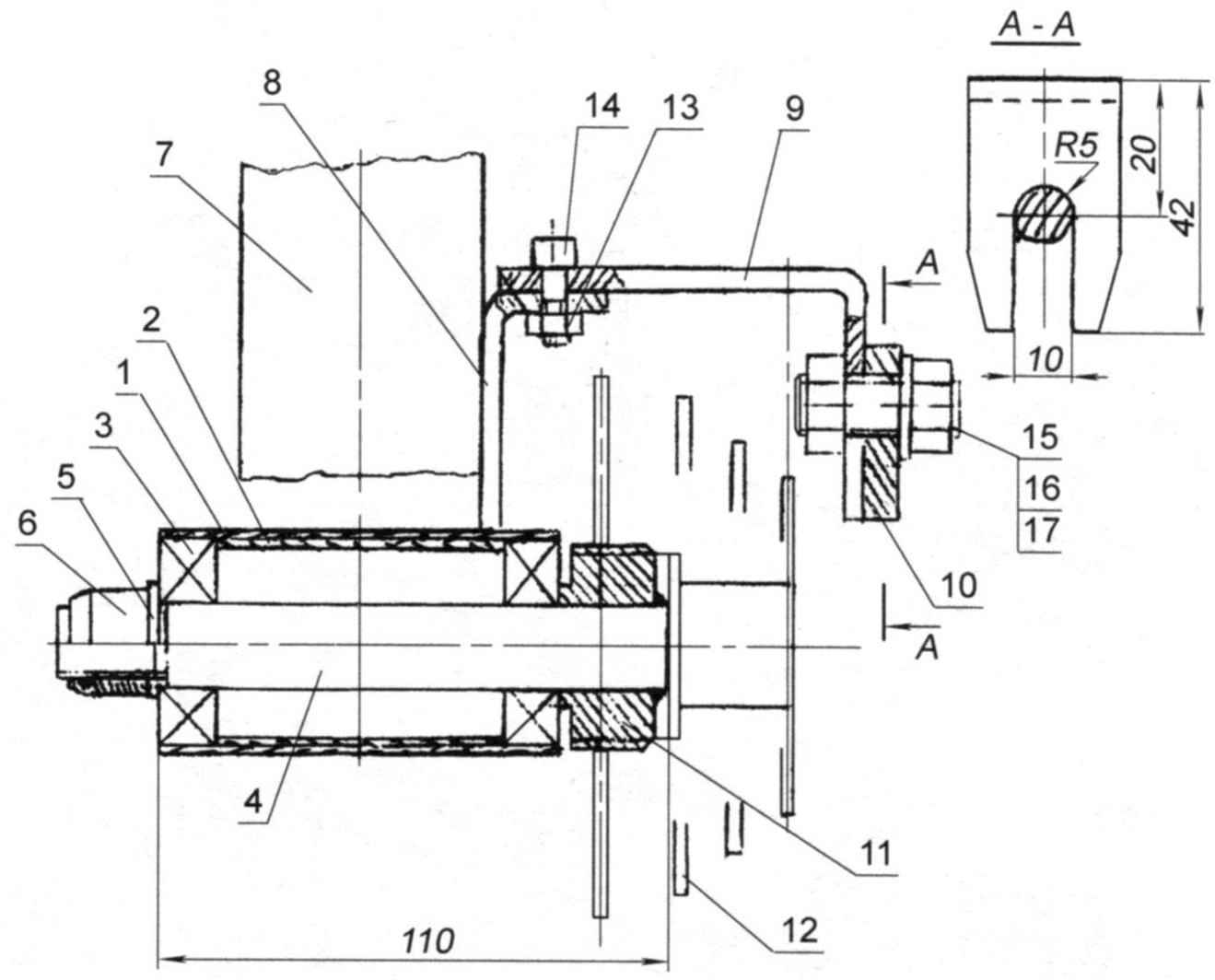
Intermediate shaft:
1 – casing (steel pipe d38x1,5);
2 – spacer (steel pipe d35x1,5);
3 – ball closed 35x16x12 bearing (2 PCs.);
4 – an intermediate shaft;
5 – washer;
6 – M12 self-locking nut with plastic insert;
7 – spinal longeron;
8 – support bracket (steel strip 25×4);
9 – switch bracket gear, intermediate shaft (steel strip 25×4);
10 – switch transmission;
11 – tip;
12 – block of asterisks (“ratchet”);
13 – nut M5 (2 PCs.);
14 – screw M5 head inner hexagon screw (2 PCs.);
15-bolt M10;
16-washer;
17-nut M10
The most difficult operation in the manufacture of knot – hole 8.5 mm diameter under the locking screw in the glass “torpedovtsy” sleeve – it termoobrabotki. So here it is better to use low-quality glasses Chinese bike or to carve them again from “raw” steel.
The insert tightly compressed in a glass sleeve. This position (in conjunction with locking screws) securely holds the wheel against axial displacement. If the connection is “loose” enough to weld these two pieces at three points.
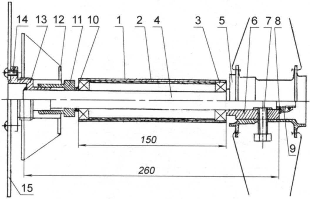
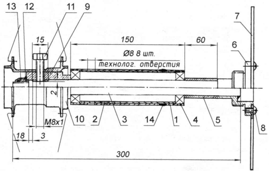
The node leading rear (right) wheels:
1 – case drive shaft shaft (steel pipe d35x1,5);
2 – spacer (steel pipe d32x1,5 mm);
3 – closed ball bearing (32 15×9,2);
4 – driveshaft (steel, circle d15);
5 – Bush of a wheel;
6 – insert wheel sleeve;
7 – locking screw М8х 1;
8 – washer;
9 – self-locking nut M12 (with plastic insert);
10 – compensator (aluminum pipe d20x2,5);
11 – the key “ratchet”;
12 – block of asterisks (“ratchet”);
13 – flange;
14 – M5 screw (4 PCs.);
15 – disc brakes (d165)
It is very difficult to ensure the coincidence of the holes for the locking bolt. So drilling a hole and threading in box it is advisable to perform in the Assembly with glass.
Expansion joints are made from aluminum tube. Their length depends on the accuracy of the manufacture of many parts and the quality of the welding frame of the velomobile and be confirmed after a rough assembling of the rear wheels. For this reason, the final balancing of the rear wheels is carried out on the assembled velomobile in place.
The node of the rear support (left) wheel:
1 – body axis;
2 – spacer (steel pipe d32x1,5);
3 – axis support wheels (steel, round d15);
4 – closed ball bearing 32x15x9 (2 PCs.);
5 – compensator (aluminum pipe d20x2,5);
6 – flange;
7 – brake disc d165;
8 – M5 screw (4 PCs.);
9 – insert wheel sleeve;
10 – Cup wheel bushings;
11 – retaining bolt M8x1;
12 – puck;
13 – self-locking nut M12 with plastic insert;
14 – “elektronaladka” (8 PCs.)
In the design of velomobiles may be possible to apply in some cases “non-engineering” technical solutions for muskurahaton one human for the purpose of simplifying the construction – they are sometimes quite acceptable. This drive is the adjustment of clearances in bearings. It is as follows:
– locking screw is weakened a quarter of a turn;
– tightening-easing self-locking nuts provided free, but without axial backlash, the rotation of the wheel;
– then re-tighten the locking screw (to lock in a flatted shaft) and nut.
It turned out that not even need to install the locknut on the screw. If the retaining bolt and nut at the same time (!) spontaneously turn to a certain angle, the wheel will shift on the shaft within the length of his flats, not more. But upon the slightest displacement of the disk brake rotor will contact the strip, slowing the movement of the velomobile, i.e. to indicate a problem with the drive. However, testing velomobiles in four test rounds (which is about 4000 km run) did not reveal a single case of spontaneous loosening of nuts.
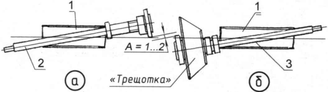
The scheme of mounting the rod (shaft and axis) in the body:
a) the installation; b) the key “ratchet”:
1 – body axle on the frame (2 PCs.);
2 — half shaft (axle) bearing left wheel;
3 – axis (shaft) of the leading right wheel
Now for the surprise that waits in the drive Assembly. It (the Assembly), as the focus or the Rubik’s cube has only one solution – a well-defined order.
First axle supporting wheels on which is mounted the compensator and the inner bearing is inserted into the housing and fixed in the position shown in the figure. Then in another case retracts the arrow shaft (axle shaft) of the drive wheel. It must be mounted consistently: “kesternich” (“ratchet” is not screwed on the threaded flange!), expansion joint and bearing. After the flanges of the shaft and the axis will raskinetsya with each other, permanently installed in the hull. Then the shaft is worn the key “ratchet” – that’s why the need for a groove in it, the latter is screwed by using the key on the flange and shaft and permanently mounted in the appropriate enclosure.
It is such a dense layout of nodes provided velomobile such a small track rear wheels. The minimum clearance of A=1 – 2 mm were determined graphically: when designing structures it is necessary to “think on paper” and all stages of its Assembly.
The steering unit. Welding holder and glass helm to perform better on the frame of the recumbent. For this guide it is necessary to drill two holes d6 and bolted holders. Then install the glass with the wheel Assembly and weld the continuous weld on the outside and dots inside.
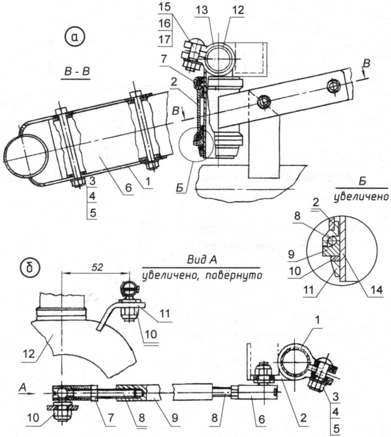
Steering:
a – steering unit;
1 – Cup holder steering wheel (steel strip 25×3);
2 – Cup wheel (steel pipe d34x2,0);
3 – bolt М6х65;
4 – washer;
5 – M6 self-locking nut with plastic insert;
6 – seat rail;
7 – Cup (2 PCs.);
8 – bearing (2 PCs.);
9 – nut;
10 – puck with us;
11 – nut-cone;
12 – bearing cone steering wheel;
13 – stem;
14 – steering column;
15 – bolt M8x1;
16 – washer;
17 – nut M8;
b – tie-rod;
1 – the steering wheel;
2 – terminal;
3 – bolt M8x1;
4 – washer;
5 – nut;
6 – the tip of the rod;
7 – lock nut of a tip M8;
8 – pin M8x1;
9 – deadlifts (dural tube);
10 – M8 self-locking nut with plastic insert;
11 – rocking fork wheel (strip 20×4);
12 – fork of the front wheel
The design of the velomobile used the wheel from the bike. Standard stem modified (cropped metal is indicated by the thin line) and welded to a shortened pin from the front fork. A glass helm, and the steering of the front wheel fork, complete with a standard set of cones, nuts, bearings, etc. Cup, it is desirable to use a from the Chinese bikes – they have a mounting diameter of 30 mm and fit tightly into the tube outer diameter 34 and a wall thickness of 2 mm.
One end of the tie rod are connected by a tip with a chair welded to the fork of the front wheel, and the second – the same tip, with a terminal mounted on the steering wheel. Ball end steering rods from a used car ZIL. The terminal is also made from the stem of a Bicycle “Kama”: remote from it the metal is indicated by a thin line. Moving the terminal along the handlebar can adjust the sensitivity of the steering mechanism to the control actions.
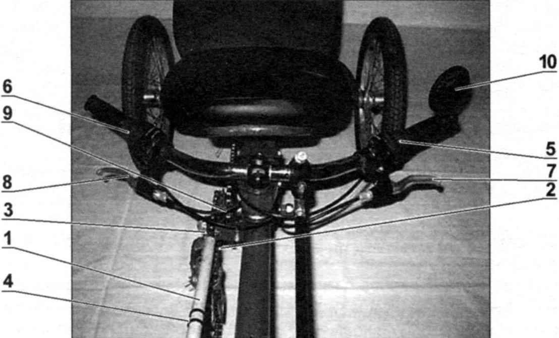
Handlebar and controls:
1 – cover circuit (PVC tube d20);
2 – guide cover (steel wire d1);
3 – screw;
4 – tie (plastic clamp, 2 PCs.);
5, 6 6 – speed shifter-shifters (2 EA.);
7, 8 trigger brake;
9 – the brake cable and gear selector in budenovskoy braid (4 PCs.);
10 – rear view mirror
Steering wheel with 6 speed shifter (shifters) control switch gear, handles and brakes at the end on the left round the rear view mirror. Their location was very convenient in the way. Shirt (braid) ropes, brakes, wheels and derailleurs attached to the frame with electrical ties. The outer casing of the brake of the drive wheel is passed through the guide tube of the frame, which made the two (the input about the steering wheel and the output is close to a cars brakes) holes with a diameter of 9 mm.
Brakes. As noted above, drive wheel -right rear, the left – only reference. But both wheels – brake. For this purpose, the inner ends of the axles of the wheels are mounted brake discs and calipers – welded to the frame brackets. The brakes are actuated via Bowden cable from Kurkov, located respectively on the right side of the steering wheel to right wheel and the left one for the left.
Welded brackets should also be performed after a rough assembling of the rear wheels. Precision installations require the bracket adapters brakes. Previously each of them are screwed in secondary provisions of the adapters with the cars brakes. Then the cars brakes are installed in position on the rotor, the pads are compressed and fixed kit with bracket, abutting the arc of the frame. Each bracket is sufficient to weld at two points on both sides.
The trunk is also a step for storage of folded recumbent upright. Terminal of the frame for interfacing of the boot is made in the following way. The segment tube is welded first, two elongated nut М6х20. Then the “grinder” is a 3 mm kerf along the path, cutting both nut in half. Then in the top pair of halves reams hole drill bit with a diameter of 6.5 mm.
The trunk:
1 – frame (steel pipe d20x1,5);
2 – holder trunk (steel pipe d20x1,5);
3 – terminal frame (steel pipe d23x1,5);
4 – round nut M6;
5 – screw М6х35;
6 – М6х20 screw with internal hexagon;
7 – the plastic plug (2 PCs.);
8 – extra long nuts M6
At the ends of the pipe – holder trunk “plug lap joint” fixed round nuts for bolts-axis. The trunk Assembly puts the frame and terminal intermittent seam welded to the rail. The ends of the framework is based on a small arc, and thus is formed a Playground for the transported cargo.
Seat. Its design is in General borrowed from the recumbent “Dandy” Kazan craftsmen Stovbunenko E. and J. Silanteva. A description of it published in “M-K” № 5 2009
The changes affected only the base of the cushion. To adjust its inclination to the arc welded a pair of parallel side cheeks of steel strip 25×2 mm. In them in a checkerboard pattern made a few holes with a pitch of 10 mm. one of them has a bolt М6х65, which serves as a focus base seat. Permutation into the other hole you can find a comfortable position.
Seat:
1 – cheek (steel strip 25×2,2);
2 – hole, staggered (3).
3 – bolt М6х65 (2 PCs.);
4 – stop focusing of the backrest (2 PCs.);
5 – clamp mounting bozinovski cables (2 PCs.)
The limiter stops the seats at the back of the velomobile “Dandy” is made of synthetic tapes with adjustable length. “Catula” he melkotsvetnoy replaced by a steel chain – step by step turned out to be easier to change the length of the limiter and, consequently, the angle of inclination of the seat back.
Chiseled customized detail: key ratchet
Before final Assembly, all the elements of the velomobile was tipped angle grinder machine (“Bulgarian”) with a flap disc to bare metal, degreased with acetone and coated with two layers of primer “rust”. Paint alkyd enamel was applied to a foam roller. With enough skill, this method is comparable in quality to spraying, but eliminates the need for special camera. Drying takes place at room temperature. While the paint dries “tack” 8 – 10, and completely – within 36 – 48 hours.
Wheel recumbent collected on single-walled aluminum rims. Tires with a smooth tread to reduce rolling resistance on the pavement, because “Catula” is intended primarily for trips around town.
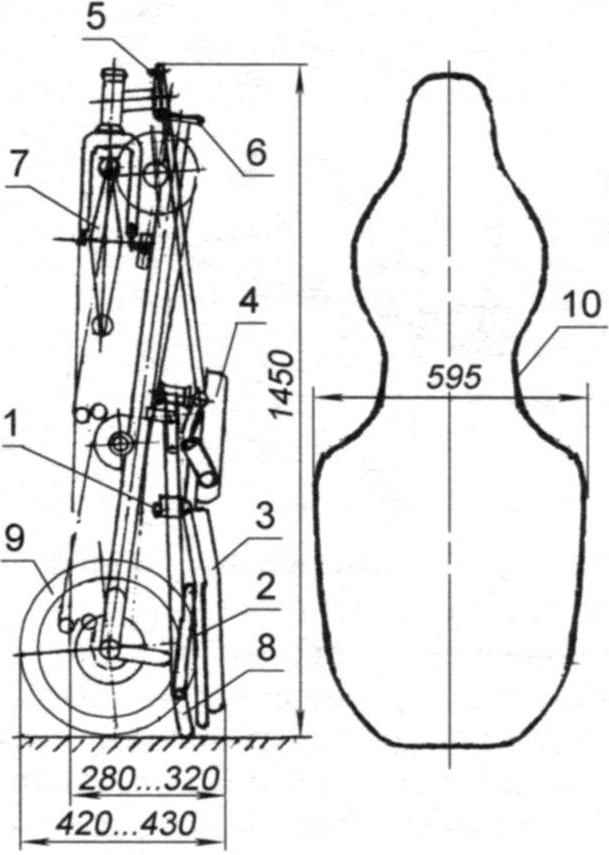
Recumbent folded and his case:
1 – a bolt-locking mechanism;
2 – the emphasis of the seatback;
3 – the seat back;
4 – the seat base;
5 – tie rod;
6 – bolt-lock hinge frame;
7 – front wheel;
8 – the trunk;
9 – rear wheels;
10 – hard case cover
Travel back to the seat is attached to the boom box and flashlight with flashing red light and to the front fork – a Bicycle headlight. They are clearly visible on the highway from afar even in the daytime. Of the devices on the velomobile – a simple bike computer, mounted on the spinal tube of the frame. Here is mounted and a holder for the flask with water.
To protect clothing from contamination of the power branch circuit of the first stage drive wearing polihlorvinila-Wai tube diameter of 20 mm. From moving in the longitudinal direction it holds the steel wire of 1 mm diameter, one end of which is fixed by screws on the support bracket, and the second is bent in the form of a paperclip drawn to a protective tube with two cable ties. This variant of the wire limiter does not prevent the tube to move with the chain left to right when shifting.
For riding in inclement weather is provided on the frame socket-terminal, which are then installed the holders mud flaps (wings) of the rear wheels.
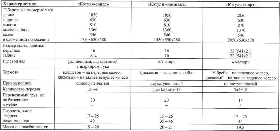
The main characteristics of velomobiles series “Catula”
In the test rounds on the recumbent was set contact the pedal, allowing more efficient to distribute the load on the legs (especially the knees) throughout the course of the connecting rod. This allowed us to take it for the day of 100 – 130 km.
To fold a recumbent should be:
a) to weaken under-seat bolt-retainer and to move the seat base forward;
– fold emphasis of the back, rotate the rack 180° and recline in his seat.
b) disconnect tie rod end from the front wheel fork;
– remove the bolt-lock hinge frame;
– turn the front fork so that the wheel is thus turned by 90°.
Now the velomobile can be stored in a vertical position resting on the rear wheel and the free ends of the frame of the trunk.
For the transport of recumbent folded width can be reduced to 320 mm (removing rear wheel), and even up to 280 mm (in this case on a recumbent you need to install the standard folding pedals). Now it is placed in a case resembling the case of the cello.
Recumbent “Katula-single” (built in 2007)
In 2007 (from the time of manufacture of the first car) at present, developed three standardized version of the velomobile:
“Katula single” with high handlebars and steering propeller shaft (hinge Hooke), folding “Katula-compact” and frisky “Katula-sport” with a more comfortable seat and narrow wheels of larger diameter. On the first two options, you can put the wheel in 16 or 20 inch. All of these models under different riders have successfully passed the 700 – to 1000-km annual test rounds of the pedal cars “the Golden ring of Russia”.
All three versions of “Catuli” well at the traffic on different roads: asphalt, grader, road. When driving on rough terrain with significant elevation changes velomobiles successfully overcome the downs slope to 10% and confidently held the road downhill, gathering speed over 50 km/h.
Despite the lack of suspension travel on the “Catole” quite comfortable. High recumbent (from seat cushion to the ground almost two feet) coupled with a flag and signal lights clearly visible on the road.
When driving in the city the active wheel and the small width allows the velomobile is easy to maneuver and literally squeeze between obstacles.
An interesting feature of the “Catuli”. Passengers overtaking car usually look for a velomobile with admiration and slight envy. So, I noticed that the seats in most “cars” are on the level, and sometimes even slightly lower than in the “Catole” that allows you to feel in the seat of the velomobile equal participant in traffic.
Despite the fact that all models are practically identical frames, each has its own peculiarities. Most nimble recumbent – “Katula-single”: takes place days at the place around the rear wheels. “Katula-compact” has good braking properties, it is possible to perform even some of the elements of figure riding on two wheels. Well, “Katula-sport”, collected on narrow wheels of large diameter with double wall aluminum rims are, of course, the fastest velomobiles in this series.
Recumbent “Katula-sport” (built in 2010)
Despite many positive qualities, the recumbent is not without drawbacks. That, in my opinion, after four seasons of operation, it would be worthwhile to change-improve the design of the velomobile? First, to reduce kilogram two to three weight (by optimizing the cross-sections, the replacement of materials and parts). Second, to increase the cross section of the shafts of the rear wheels up to a diameter of 16 mm (there is a feeling when driving that on the ground the shafts a little “play” (elastically deformed) and hinder movement. And the last set removable canopy fairing to use the velomobile in any weather.
That’s all the secrets of the box “musical instrument”.
In conclusion, I want to say that one canadian firm is also interested in the design of the velomobile “Ketels” as the chassis, setting it on a fiberglass cabin of its own design and began producing urban velomobile called “Aurora”. Modernization “Katuli” it can also go this route. But it makes more sense, in my opinion, is to provide a foldable version of a tent made of thin waterproof fabric in a lightweight collapsible frame.
V. UL
Recommend to read
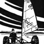 FOR A SAILBOAT SKIING
When going on a long journey, skier, usually relying only on its own strength. However, it is possible to summon the wind, erecting for this purpose a sailing ship. To collect such...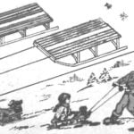 THE SLED WITH RUBBER BAND
That the cord does not interfere with the movement of the sled during the descent from the mountain, I propose to make it retractable. For this to end you need to tie the two segments of...
