
 Times of shortage, it would seem, were but a grandmother for her grandchildren the old-fashioned way tend to knit warm clothes, especially socks and mittens. The best material for these products, of course, yarn of wool. Probably, it would be possible to buy, however, and spinning wool grandma prefer. Probably in this yarn absorbs and permanently retains the warmth of my grandmother’s hands and because of that Samovodene things are so good warm.
But the fingers of women are not so obedient and agile, and because it would be nice for them operation to mechanize spinning. Foot-operated spinning wheel in this case is also of particular advantages does not give. So the best thing to do electroparka, moreover, that this mechanism is not so complex to manufacture. The elements of the circuits — are not scarce, and the details of the mechanisms able to produce yourself.
The unifying element of electroplate is the base, made of duralumin plate 10 mm thick (you can make it out of the PCB, Micarta, other suitable materials). The base serves both as a chassis on which are mounted a massive part of the management electrical diagrams: driven electric motor, power transformer, transistor with heat sink, diode rectifier bridge. The coordinates of the mounting holes on the drawing, the base here is only for the bracket of the motor because the pulley handle and the handle driven pulleys spinning wheel must be in the same vertical plane. Other elements can be positioned in accordance with the General arrangement drawing or even in a different order, drilled at the base of the holes for attaching them in place.
To the side edges of the base are attached with M4 screws wpoty support pillar underlying the shaft with all parts of spinning wheels. The Desk is made from steel sheet 4 mm thick and differ from one another only by the size of the grooves at opposite ends of the shaft.
To the sole (the bottom plane) of the base at the corners glued low rubber lugs shock absorbers.
Elektropryalka (on the top view, the position under the casing):
1 — casing (steel sheet s0,7); 2 support strut (steel sheet s4, 2 pieces); 3 shaft (bronze, round 14); 4 —hooks (steel wire Ø1,5, 26 pieces); 5 —coil disk (Micarta, sheet s10); 6 — bushing spool (bronze, round 12); 7, the small driven pulley (Micarta, sheet s15); 8 — big driven pulley (Micarta, a sheet s12); 9 — nut M6 (left, duraluminum D16); 10 — belt (tape); 11 – bagel (Micarta, sheet s18); 12 — base-chassis (aluminum, sheet s10); 13 — diode rectifier bridge; 14 — radiator transistor; 15 — bracket-holder motor (duraluminum D16); 16 — motor DPR-52; 17 – drive pulley; 18 — M4 nut of fastening of a pulley; 19 switch modes (spin-twist) — change the rotation of the motor to reverse (toggle switch П2Т-2); 20 a power switch (toggle switch MT1); 21—a variable resistor JS4-2M; 22 — transformer TCEs 110ЛМ; 23 — the protective sleeve (rubber tube)
Electrical elements and devices mounted on the chassis which are covered with a casing of steel 0,7 mm sheet. The casing is screwed to the front and rear edges of the base. On the front (front) panel of the casing removed controls and alarm: toggle switches on-off of power and change modes (spin-twist), led, potentiometer.
Rotation of the shaft spinning wheels is from the electric motor DPR-52. The motor is inserted into the hole of the bracket and sandwiched on top by two M3 screws, and the bracket dragged to the base by four screws M4. I have an explanation about the operation of the motor. The passport he needs to be fed a voltage of 27 V. But I have tested that the motor works well and from a lower voltage up to 5 V. Thus, the change of the motor supply voltage through the variable resistor (potentiometer) affects only the increase or decrease in the number of revolutions of the motor.
On the shaft of the motor is mounted and secured by nut M4 drive pulley belt transmissions with two streams. Two rubber belt, replacing V-belts transmit torque to the driven pulleys, one of which is mounted on a shaft and the other on the coil (Babyn) spinning wheel. The driven pulleys are slightly different in diameter — the one on the coil, it a little more. The belt can be used from the old VCR or even those which tie bundles of banknotes. The tension of the belt should not be strong.
In the hole of the side plates, through which the power cable, inserted a safety rubber tube-sleeve.
The dimensions of the parts of the spinning mechanism taken from vintage foot operated spinning wheel. The mechanism consists of a slider and a coil. The slider form a bagel made of Micarta and the shaft of bronze (and brass). The bagel is placed on the shaft by an epoxy glue. In each branch is explored from different sides inserted (epoxy glue) to a pre-drilled blind holes (cavities) 12 hooks made of steel 1,5 mm wire, one hook in the jumper, near the bore holes.
Pedal:
1 — base (duralumin D16, sheet s6); 2 housing (aluminum, sheet s1); 3 — a cover (aluminium sheet s1); 4 — locking screw M3 (2 PCs); 5 — lead (steel 20, a sheet s1,5); 6 — Cam (steel 20, the sheet s10); 7 — pin (screw M4); 8 — potentiometer; 9 — angle bracket potentiometer (sheet s2); 10 — the screw mount bracket M3 (4 PCs.); 11 — angled bracket of the leash (sheet s2); 12 — the axis of the carrier (bolt M4); 13 — spring (normally compressed); 14 — anchor spring (screw M3); 15 — lock nut M10 potentiometer
The coil consists of a bronze (or brass) bushing and is mounted (epoxy glue) on the end disk is made of Micarta. On the other end of the sleeve is also epoxy mounted a small drive plate of the drive. Coil freely fits on the shaft, and its end is screwed and tightened nut M6 left-hand thread larger driven pulley. Then on the shaft throwing the belt, the mechanism “method bias” is inserted in the slots of the uprights, and a belt put on the pulleys.
Before you start to spin, you need to pass a strong string with a length of about 30 cm through an axial bore in the shaft, hooks bagel and fix its end on the coil. The other end of the thread to grab the beginning of the prepared wool in the beam. You can then start the spinning wheel, by turning it on and turning little knob of potentiometer, and to spin the yarn, pulling the wool from the beam so much that the thread was the correct thickness.
For consistent and uniform filling of the coil when it’s time to throw the yarn from hook to hook. With the acquisition of skills can increase the potentiometer and the rotational speed of the mechanism.
Due to the fact that the pulleys on the reel and the shaft have different diameters, the roll will rotate slightly slower than the coil, providing the thread tension.
The direction of rotation of the mechanism (when viewed from the left): when the spinning is clockwise when ssuchivanie — on the contrary.
Continuous operation of the spinning wheel — about three hours.
For convenience of work at the spinning-wheel it is better to provide a pedal in which it is necessary to mount potentiometer R21 (see control wiring diagram) to change the voltage supplied to the motor, and thereby to increase or decrease the speed by pressing the foot.
The design of the pedal is not too difficult. However, you should not allow large deviations from nominal sizes: the smaller the gaps between the interacting parts, the better to work the pedal.
Managing the electrical circuit of the spinning wheel
Pedal on the basis of duralumin sheet thickness of 6 mm is fitted with two support bracket in which are mounted the corresponding parts: the leash and the variable resistor. The potentiometer is secured by its locknut, and the shaft is worn and the stopper screw M3 Cam. In another hole of the Cam pin is inserted (screw M4) and also the stopper screw M3. This locking screw clings to one end of the spring, the other end in the tense position of the spring is also a M3 screw is attached to the base.
In the other bracket, on the axle, set the leash in the groove of which Cam a pin is put. After that, the base mechanism with the housing, and the housing is covered with a lid.
In the side wall of the body has a hole with a diameter of 8 mm, through which the wires from the potentiometer goes out and through contact RS-4 is included in the control circuit of the spinning wheel.
Variable resistor must be installed in the corner bracket so that when you turn on the power supply at the pressed pedal position of the electric motor is supplied voltage of about 5 V.
With this setting of the potentiometer of the angle of rotation of its shaft, and hence of growth supplied to the motor voltage is enough for normal operation of the spinning wheel.
Another important value is the selection of the spring, which shouldn’t be too hard, but could always return the Cam with a leash and a cap in the starting position.
Y. KURBAKOV, Tula
Recommend to read
 INVENTING… THE WHEEL
At this stage of the work, outline the design of the actuator, which provides translational movement of the model. Let's start with the analysis of the already known mechanisms, which...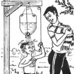 THOUGH RUKOMOINIKOV, THOUGH — SHOWER
Indeed, the proposed "wash" the device for use in the country may be universal — it will depend on used plastic containers: a two-liter bottle enough to wash hands or dishes, and...
