THE WATCHMAN AND ILLUMINATOR

THE WATCHMAN AND ILLUMINATORAs you know, the greater the number of elements in the design, so it is less reliable. To increase the reliability of electronic devices and selection circuitry. This will be the conversation below.

 
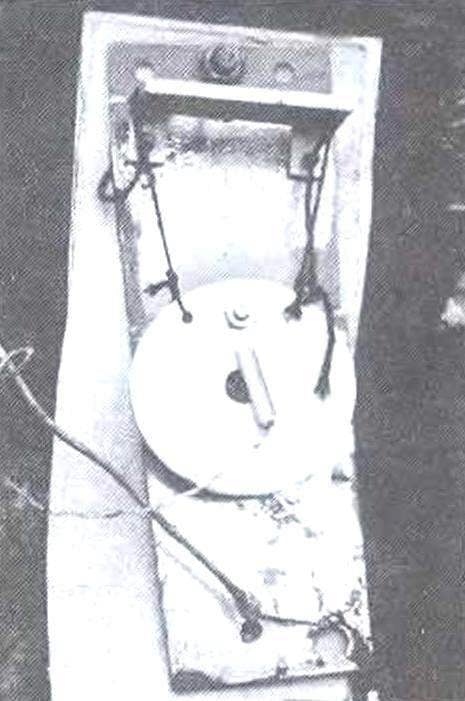
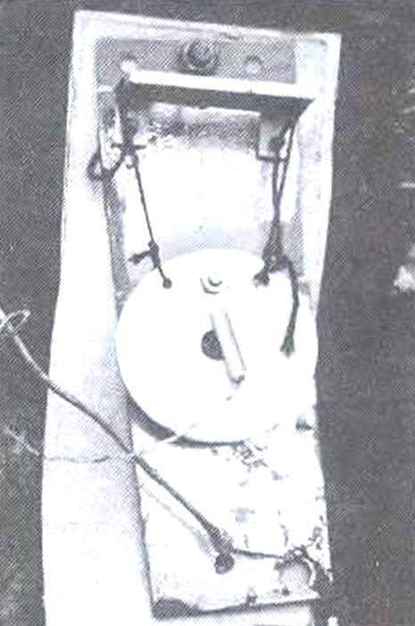
For several years the authors have used to protect separately stasey unheated garage guard device for industrial production with a sensor, which was normally closed contacts. The design of the sensor used a steel ball and spring-loaded contacts, and the sensor, despite regular sealing gasket, not even in extreme cold refused to work. The very same watchdog had a minimum of parts, and therefore never fail. Its simplified schematic diagram is shown in Fig.1. When breakage of the line or its short circuit relay disconnected and rang the bell. It was therefore decided to replace the device this sensor is on the other with normally open contacts (see Fig.1, 2 and photo). During the winter of last year there was not a single rejection watchdog the device even in quite severe frosts.
 
It would be unwise, having a two-wire line to the garage for the guard device not to fail there and network voltage. After all, lighting inside the garage, charge the battery, plug in a circular saw or grinder — all this can be done only from the network That was implemented In Fig.S shows a diagram of a guard device elements of the switching sensor and is interlocked with it’s line of household lighting SEG voltage of 220 V.
But back to the sensor design (see Fig.2 and photos). On the plate 1 of foil fiberglass and the top is bolted M3 corner bracket 2. With the help of lavsan threads 3 to him is suspended a brass weight pendulum-4. The lower part of the plate 1 are insulated (slit foil) from the bracket and point of attachment to the gate of the garage. There, at the bottom, a diode rectifier VD2. Bob-a pendulum is connected with the lower part of plate 1 wire MGTF 0,12. Wire line extending from the sensor attached to the gate of autoerotica (clay). This line is suitable to switch IS (type TP-1-2) inside the garage, which communicates the sensor and the power outlet
 
Fig. 1. A circuit diagram of a watchdog device
 
Fig. 1. A circuit diagram of a watchdog device:
 
A gauge of industrial production with normally closed contacts;
B—a homemade sensor with normally open contacts

 
Fig. 2. Diagram of a homemade sensor with normally open contacts
 
Fig. 2. Diagram of a homemade sensor with normally open contacts:
 
1 — base (foiled textolite plate s1); 2— bracket (dural area 40х20); 3— suspension (nylon thread, 2pcs); 4 — Bob of the pendulum (bronze plate); 5— prong weight pendulum with the base (wire MGTF 0,12); 6 — rectifier (diode); 7 — wire network line 220 (“field” wire)

 
Now. how the device works. Power is supplied via a galvanically isolating step-down transformer (very important). The voltage on the secondary winding is 18 — 21 V. the Diode VD2, which is the end of the line, rectifies the voltage which is supplied to two turnips RES-55A (602). Parallel to both the relay includes a capacitor for smoothing the ripple.
Before starting the device, ensure that the switch ЅА2 is set to “sensor”. Now, the voltage applied to the network to the device a switch 1. Immediately begin ringing the call through the normally closed contacts K2 turnips. Now press the “start” button. Both relays in the case of health line up on the lock. The bell ceases to ring. When you try to open the gate is triggered by a pendulum sensor, which closes the rectifier diode. Alternating voltage relay, translates them to a disabled state. Scheme rasplachivaetsya. Ring g call. In the event of breakage of pinii voltage to the relays is not supplied, will also be ringing the bell.
 
In order to apply voltage to the outlet in the garage, and should it translate AS toggle switch to “network”. Now (and only now) can be translated thumper ЅА2 to “sing” and turn the unit on. Lights led VD1. Off the mains in reverse order.
 
Fig. 3. A circuit diagram of a guard device, combined with a line of household lighting network 220 V
 
Fig. 3. A circuit diagram of a guard device, combined with a line of household lighting network 220 V
 
This device applied the doorbell of continuous operation.
 
The device used two relay RES-55A, because each of them has only one group of switching contacts. It is possible to use other types of relays, for example, RES-9 RES-47 and the other with two groups of switching contacts.
 
I. finally, the line is drawn in the “field” wire. He has a very high mechanical and thermal strength. During the great Patriotic war, this wire has won fame essential in all sub-divisions, which were subjected to wired connection.
 
To make sure that the line in the garage is switched to position “network” should include the device “sensor”. If the bell rings, then switch to “network” implemented.
 
A. PARTIN, L. MARTINA Ekaterinburg

Recommend to read

  • BETWEEN THE FLOOR AND CEILINGBETWEEN THE FLOOR AND CEILING
    Every thing in the house requires a certain space. Updated your library, increasing the number of objects or devices for work and leisure — in each case the problem arises of their...
  • “TREAT” TRACK“TREAT” TRACK
    Wow, what a shame — cracked and crumbled concrete path on your country station! To talk about the fact that slim was a layer of mortar or the soil slipped, too late... But you shouldn't...