VOLTAGE CONVERTER FOR MS

VOLTAGE CONVERTER FOR MSDesigning electronic devices on integrated circuits, radio Amateurs often use to display the information indicators IN gas-1 — IN-16. They usually feed from the mains AC voltage of 220 V or from a separate winding of the transformer. Consequently, the instrument is “tied” to the grid and they can not be used in the field.

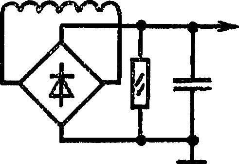
The issue of autonomy will help solve the voltage Converter, which allows you to get from the power source +5 V DC voltage +200 V, sufficient power to connect the six indicators type IN-1. The basis of the Converter equals the multivibrator logic IC К155ЛА13 open collector and high load capacity. MS elements DD1.1, DD1.3 and DD1.2, DD1.4 (see circuit diagram) connected in parallel to increase the output power of the Converter.
Schematic diagram of the voltage Converter.
 
How does such a Converter? When, for example, the element DD1.1 (DD1.3) is in a state of logical 1, and the element DD1.2 (DD1.4) is logic 0, capacitor C1 is charged through a resistance of half of the primary winding of the transformer T1 and outputs the first and second elements. As soon as the voltage at the input DD1.1 (DD1.3) reaches a threshold, the two elements are switched to the opposite state and capacitor C1 begins to discharge through the output circuit DD1.2 (DD1.4), the resistance of the other half of the primary winding T1 and the output circuit of the first element. When the input voltage DD1.1 (DD1.3) drops to the threshold, the elements once again switch to the opposite state. At the time of the switching elements in the transformer there are current pulses, rising in the secondary winding and supplied to the diode bridge VD1 —VD4.
 
Transformer T1 is made on armor core scalping ferrite 2000NM mark. I winding contains 100 turns of PEV 0,16 proada with tap from the middle, a winding of II — 2,800 turns of PEV 0,07.
 
To eliminate radio frequency interference, the inverter should feed through the l-shaped LC-Fitr. As part of L you can apply a choke type DM-inductance 0.1 µh 150…180 or make an improvised by winding 100 turns of wire PEV 0,2 ka ring core made of ferrite 1000 NM with an external Ø 10 mm and thickness 2 mm. the Element is composed of two capacitors connected in parallel, oxide…capacity of 100 and 200 µf ceramic 6800 pF to 0.01 µf….
The voltage Converter is mounted on Pechatny Board (see picture) size 20X30 mm foil fiberglass thickness of 1…1.5 mm.

 
Circuit Board of inverter with the layout of the elements.
The circuit Board of the Converter with the layout of the elements.
 
Mikhail POZHIDAEV, village Verkhnyaya Kolva, the Perm region.

Recommend to read

  • SNOWMOBILE “MORGANOK”SNOWMOBILE “MORGANOK”
    This machine is designed and built by the young craftsmen and DHT Gorky aircraft plant them. S. Ordzhonikidze, under the guidance of the teacher L. N. Pisarevskogo. The boys set a goal...
  • DRIVE ON THE “CIRCULAR SAW”DRIVE ON THE “CIRCULAR SAW”
    On a circular Pipa can not only dissolve a wooden Board in straight lines, but cut discs of any diameter from sheet material. For this you need only do a simple device-a plywood plate,...