
 Many designs of metal collected with the use of electric welding. I made this several machines, and one was the most successful and easy to use. I offer welding transformer with electronic current control. It has no moving parts that require a high build quality and vibration. The control unit allows you to smoothly adjust the welding current by turning the potentiometer knob. At the same time all the range of the arc is burning stably. I think this design should be of interest to readers of the journal.
Figure 1 is a circuit diagram of the welding machine. It includes: welding transformer T3; power rectifier thyristors VS3, VS4; a rectifier to power the arc of the duty diode VD6 — VD9, smoothing choke L1, and the unit for control of power thyristors transistors VT1 — VT5.
The main arc is powered by a rectifier thyristor VS3, VS4; the value of the welding current is changed by changing the angle of thyristors.
When the power thyristors are closed, the electric welding arc is provided by the circuit feeding diode VD6 — VD9 and inductor L1.
Power rectifier has a falling external characteristic. Rectifier duty arc has steeply dipping external characteristic due to the inductor L1 in the circuit, the arc maintains continuous current that provides a stable burning arc and prevents shedding of the coating of the electrodes.
The control circuit consists of power transformer T1, rectifier diodes VD1, synchronization circuit of transistors VT1 and VT5, the phase-shifting device transistors VT3, VT4, comparator transistor VT2, the circuit of the meter of the welding current at the current transformer T4, the control circuit power thyristors the thyristors VS1 and VS2.
Scheme of the synchronization transistors VT1, VT5 is designed to discharge the capacitance C3 of the phase-shifting device at the beginning of each half cycle of the supply voltage network. At the moment when the voltage is 0, the base of the transistor VT1 is 0 (it is closed), and VT5 is open and C3 is discharged; in all other cases, VT5 closed.
At the beginning of each half cycle of the supply voltage capacitor C3 is charged via the VT2 and R8; in the moment when the voltage on C3 will be equal to the voltage at the base of the transistor VT3 is opened, VT4 and C3 is discharged to the first winding of the pulse transformer T2. With the windings II and III of the current pulse opens the thyristor VS1 or VS2 (opens the thyristor, the anode of which includes a positive half wave voltage). Current control windings III or IV of the transformer T1 through the open thyristor VS1 or VS2 is supplied to the power thyristor VS3 or VS4. Of these thyristors offer the control electrode through which flows the control current. The latter is limited by the resistors R14 and R15. Through the open thyristor VS3 (VS4) current flows from the welding arc, it is measured by current transformer T4 and through the feedback circuit VD5, R17, C4, R18, R20, R7 is supplied to the comparison circuit of transistor VT2. The voltage of the resistor R20 is compared to the voltage at point “A” of the comparison circuit. The VT2 transistor changes its internal resistance (it works in active mode) depending on the voltage difference between point “A” and the resistor R20. If the current through the welding arc is increased by more than the specified control unit, the internal resistance VT2 increases, the capacitor C1 is charged slower, the angle of inclusion of power thyristors increases and thus the current through the welding arc is reduced.
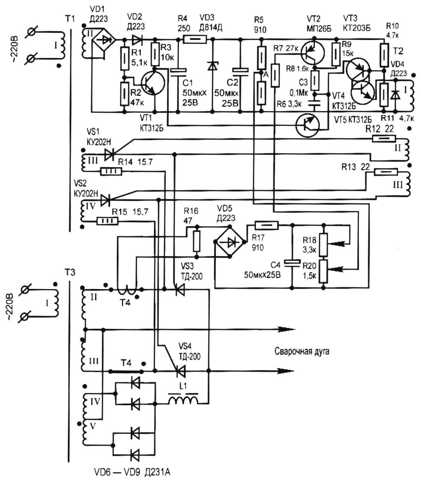
Fig. 1. A circuit diagram of a welding apparatus with electronic current regulation and a mains voltage of 220 V
In the case of reducing the welding current is lower than set by the control unit, the reverse process occurs: the angle of inclusion of power thyristors is reduced and, consequently, the arc current increases. Thus the regulation of welding current.
The current arc is set from the control panel by turning the resistor R20. In the process of arc gap between the electrode end and welding product varies, thus changing the arc voltage. In some cases (with a large gap) it becomes greater than the voltage of the power rectifier, and then the arc begins to eat from the rectifier duty of the arc, and the power thyristors are closed. In the case of reducing the length of the welding arc power thyristors open again, as during the half-cycle across the control electrode of the thyristor current flows control.
The transformer T1 can be any capacity, but not less than 20 W, the primary winding of the I — 220 volts, winding II on 24 volts, the wire diameter not less than 0.13 mm, winding III and IV — for a voltage of 12 volts, the wire diameter not less than 0.25 mm.
The transformer T2 is wound on a core of ferrite К20х10х5 2000 nm. Windings I, II, III — 50 turns of wire sew-1 0.2 mm in diameter.
The core of the transformer T3 — electrical cold-rolled steel of grade 3404 thickness of 0.35 mm (the dimensions shown in Fig.2). Winding I — 162 revolution: two sections 81 round copper wire size 8 mm2 (2×4 mm). Each coil II and III — 32 turns: consists of two sections of 16 turns of copper wire with cross section of 15 mm2 (3×5 mm). Windings I, II, III have insulation of fiberglass impregnated with heat-resistant varnish. Winding IV, V — 93 round enameled wire with a diameter of 1.7 mm.
As of the current transformer T4 is taken from the core of the current transformer TC 200, 100/5. It has two primary windings, one coil of a cross section of 15 mm2. As wire you can use welding cable or other stranded wire in isolation. The secondary winding is 400 turns of enameled wire with a diameter of 0.5 mm. It is wound on the frame from the old secondary winding.
The core of inductor L1 is in electrical steel; the cross section of the magnetic circuit (passing through coil) is not less than 12 cm2 with non-magnetic gap of 1 mm. the Number of turns of enameled wire with a diameter of 2.24 mm — 68.
The electronic circuit is not critical to the radio, except for VT3 and VT4 (a pair of these transistors should be analog of the dynistor). Resistor R20 should have a knob to regulate the welding current. Resistor R16 is of PEV 10. Resistor R15 (R14) is made up of three parallel-watt resistors 47 Ohms each.
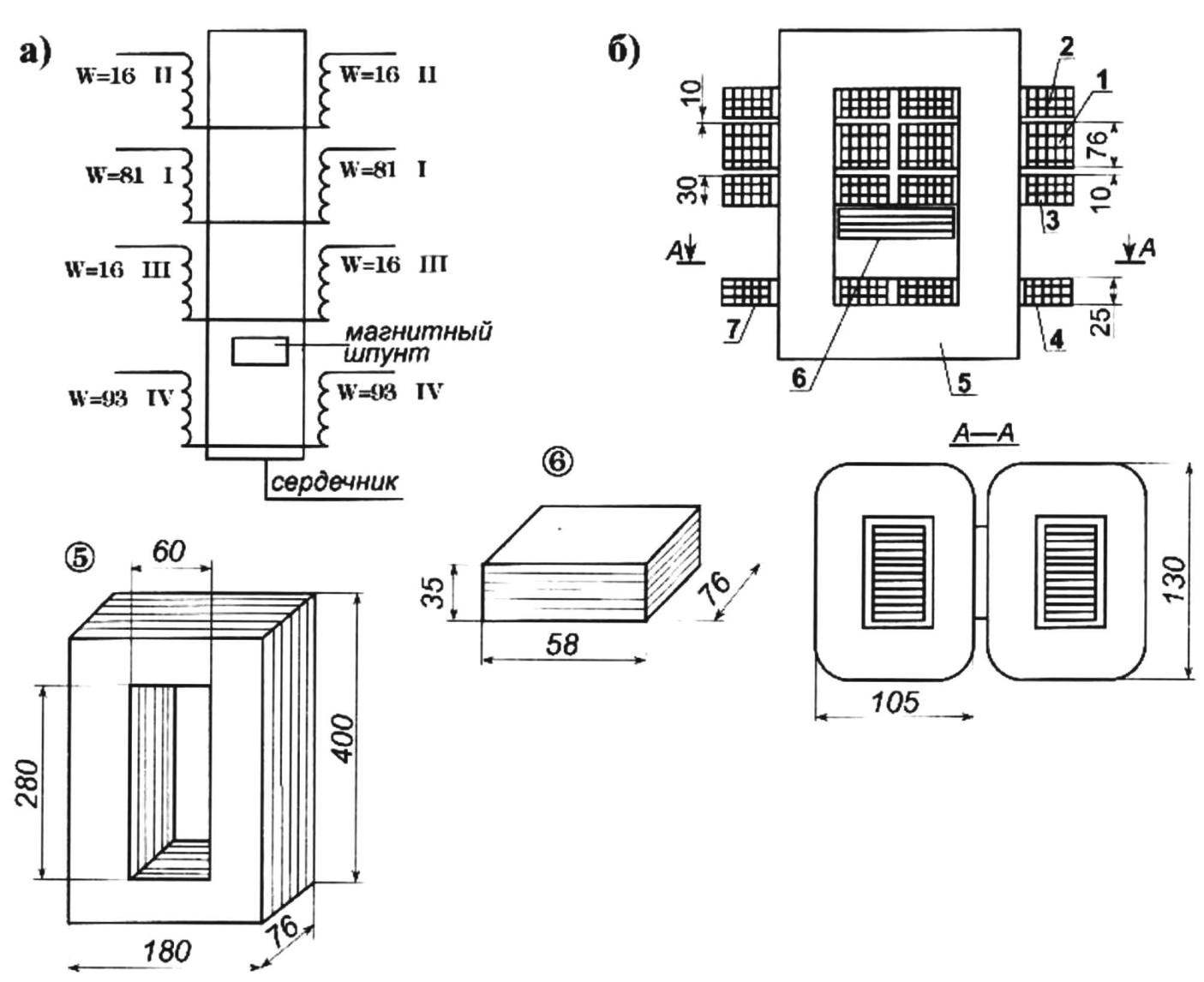
Fig. 2. Welding transformer T3 (electric (a) physical and (b) layout of the windings on the magnetic core):
1 — winding I (two sections 81 round copper wire 8 mm2); 2,3 — windings II and III (each of the two sections of 16 turns of copper wire with cross section of 15 mm2); 4,7 — winding V and IV (but 93 round enameled wire Ø1,7); 5 — core (cold-rolled steel of grade 3404, sheet s0,35); 6 — magnetic shunt
Debugging of the welding transformer is performed one block at a time. First, he collected and included in the network through the fuse is not less than 30 A. Then checked the voltage on the secondary windings: II and III —up to 45 volts, and you must enable them under; the windings IV and V to 90 volts (according to inclusion). In series with the power thyristor included single-turn winding of the current transformer T4 in such a way that it worked in the mode of magnetization reversal.
After Assembly of the control unit check the pulses at the output T2 and the synchronization scheme. For checks instead of VT2 transistor is parallel to R9 should put the variable soprotivlenie 20 kW and by modifying its value, check for a change in the angle of inclusion of the analog of the dynistor. Then going the whole scheme. In the welding arc circuit is an ammeter with a current full deflection 150 — 200 A. When you weld metal it is necessary to adjust the resistor R18 so that when you turn the knob of the variable resistor R20 welding current was varied from 45 to 140 A.
Power thyristors are mounted on standard heat sinks; diodes VD6 — VD9 installed four radiator with an area of 30 cm2 each.
The welding transformer has been successfully and reliably operated since 1993 to this day, electronic control of welding current is very convenient when welding, especially in different spatial positions of the welding seam.
Technical characteristics of the welding transformer with electronic current regulation:
The voltage, V………………………….220
The limits of regulation
the welding current, And……………………..45 — 140
The open-circuit voltage
power arc, …………………………………….42
The open-circuit voltage
the duty of the arc, ………………………………….87
The current makeup And……………………………………….15
N. SYSUEV, Samara
Literature:
1. D. Priymak. To help the radio. Radio, 1989, №5. p. 79.
2. M. I. Sachs, B. A. Kazansky, A. A. Pechenin. Transformers for electric arc welding. — Leningrad: Energoatomizdat, 1988
3. V. M. Rybakov. Arc and gas welding. — Moscow: “Higher school”, 1986
Recommend to read
 RESCUED BUTTONS
Once I decided to put on his acoustic guitar strings electric from the tension of the tailpiece cracked. This was because the new strings had not cylindrical, and conical head. Buried in...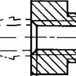 AN AUTOMATIC PUMP FOR BIKE
Pump chamber of a Bicycle wheel, for example after repair or tire, the operation is quite tedious because of the low performance of the supplied pump. Besides, there are pumps, hose...
