KATYUSHA BM-13

KATYUSHA BM-13Scale model 1:25.

THE JET SYSTEM OF VOLLEY FIRE BM-13 “KATYUSHA” ON THE CHASSIS.

“Katyusha” — the informal collective name mobile rocket launchers BM-8 (82 mm) and BM-13 (132 mm). Such plants are actively used in the USSR during the Second World war.

Back in 1916. combat missile for smokeless powder (the prototype of the later missile) was invented by Ivan Platonovich grave. In 1924. he got on a missile and a charge of patent No. 122. Further work on the creation of rockets on smokeless powder continued until the great Patriotic war.

The development team consisted of Sergei Korolev. In March 1941, were conducted successful field tests of BM-13 with a projectile M-13, and already on June 21 signed a resolution to their mass production. On the night of 30 June 1941 at plant of a name of Komintern in Voronezh was collected the first two combat launchers BM-13. They were originally mounted on chassis ZIS-5, but the use of this chassis was considered a failure and it was replaced by the ZIS-6. Subsequently, BM-13 (BM-13N) was mounted only on Studebaker (Studbacker-US6). Experimental artillery battery of seven machines under the command of captain I. Flerov was first used against the German army at the railway junction town of Orsha on 14 July 1941. The first eight regiments of 36 cars was formed on 8 August 1941. Improved modification of BM-13N was created in 1943 to the end of the Second world war was made about 1800 of such instruments. The range is about 5 km.

The weapon was inaccurate, but very effective when massed use. Important was the emotional effect: during the salvo all missiles were produced almost simultaneously – in just a few seconds territory in the target area literally plowed heavy rockets. In this deafening howl, which lifted the rocket during flight, literally crazy. Those who did not die during attack, often could not resist, as were shell-shocked, stunned, completely mentally depressed. Mobility allows you to quickly change the position and avoid the retaliation of the enemy.

On each machine was a box with explosives and a fuse. In the case of the risk of seizure of equipment by the enemy the crew was required to blow it up and thereby destroy the reactive system.

The name “Katyusha” came from the label “CAT” (“Kostikova automatic thermite”) applied on a rocket with an incendiary filling. And since the emergence of weapons in combat units coincided with the popularity of the song “Katyusha”, he caught the name.

We propose to build a model of the guards mortar BM-13 “Katyusha” on the platform of the Studebaker (Studbacker-US6).
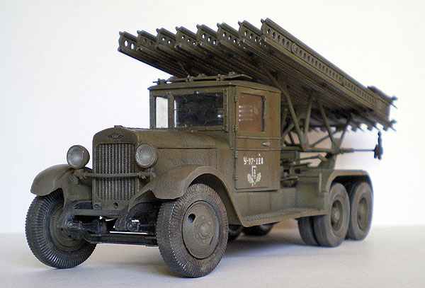
 

SpecificationsKATYUSHA BM-13

Engine—6 cylinder,inline.

The working volume -5240 cmH.

Power to 95 HP at 2500 rpm.

The capacity of -2.5 T.

Weight -4850 kg.

Speed is 72 km/hour.

Rocket M-13

Caliber,mm -132

Projectile weight, kg -42,3

Weight of warhead, kg -21,3

The mass of the explosive,kg -4,9

Firing range-max, km -8,47

Production time volley, h 7-10.


Assembly instructions

1. Frame

Rama is a diagram of the items 1-6. The bends are marked in grey. Using glue parts 7 9 front bumper and tow hooks 8 gather the back part of the 10-15 parts, the part 13 is folded with a tube. For convenience, you can attach a strip of cardboard with a thickness of 1 mm. in detail 10.

Now you can assemble the suspension. First, parts of 30-36 going tri gear. Then, each is passed through the axis 29, 69 and 108. Then, with the help of crosspieces 50, glued the propeller shafts 71 and 51,70. The crosspiece 50 is easier to glue if you invest inside carved from cardboard detail the shape of the cross. From parts 72-1 and 72-2 is going to transfer box. From parts 72-4 and 72-8 going transmission and by means of crosspieces 50 and cardan 72-3 is attached to the transfer case. Two of the rear axle with parts 66 are glued to the frame parts 2 and with the help of springs. Rear springs going from the strips 21, which are pre-folded in half, glued together and then glued to each other. After you have assembled the package of springs, they should be given a semicircular shape. Is parts 25 and 26 can apply a toothpick.


2. Wheel

The drives for the rear wheels are assembled from parts 203-206. Separately cut the nuts 90 and glued to the disk. Then collect the tire from parts 209-212. After assembling the wheels glued to axles 29 and 69.

The drives for the front wheels going a bit differently if you want to make them swivel. On the front wheels is added to part 208. The rotation mechanism is collected as follows: item 95 rolled into a ring and is inserted inside деталь92 and the fixing part 94. Item 92 must rotate freely within the part 95. Then, to the axis 108 is attached to the part 92. Inside the disk is attached to the item 102 and is attached to it item 99. After that, the disc is worn tire. The order of Assembly clear from the diagram.


3. Engine

The engine Assembly should start with the body 111. Then it is attached additional equipment. To facilitate the bonding parts 112 is glued inside cut from cardboard with a thickness of 1mm, the shape of the item. The rest of the details are pasted in the order of numbering. After engine parts 137-140 collect the radiator. After assembling the radiator and the engine is attached to the frame engine to the workpiece 5 and the radiator by means of part 141. After that the radiator through the pipe, glued the parts 142 to 146 is attached to the engine.


4. Cabin

First assemble the cab interior. First collect the instrument panel 180, which is bonded to the front wall 186, and gender 185. Collect the wheel 192 and steering shaft 192-1. The levers 194 folded in half and stuck together, so do the pedals 195 . Finished the pedals and levers glued according to the scheme. Last, glue the seat (198-199) and the interior of the cabin ready. Now proceed to the outer skin of the cab. The cab roof is assembled from parts 149-150. To it is attached inside the ceiling 149-1. Then the rear wall 148 and side walls 160. The door folded and glued. Between the halves of the door are pasted the loop. Glue glass cut from transparencies the templates on the last page and glue the wipers 197. Then assemble the hood. The front wing is glued together from part 182. On the reverse side podklyuchaetsya detail 182-1. To it glue side wall 181. Collected under the scheme of the hood 180 and glue in place. Glue two lamps 201 and 202 one smaller, which is spruce side and glue the grille 200. Behind the cab, fix the gas tank 214-216.

5. Launcher

The launcher Assembly begins with the Assembly of the base 218, which with parts 217 is attached to the vehicle frame. To the front of the pasted control mechanisms and 221-226 227-231. Collect rails for missiles. They consist of three parts. Details 253 253-1 and bend to get turned sideways letter P and glued together, then holes are cut, then the top and bottom are glued strips 254. Between the rails are assembled with parts 257 coiled tube. In accordance with the scheme collected tubular structure, which guides glued to the base of the launcher. Details for bonding pre-formed on a mandrel with a diameter of 2mm and glue the pad to the frame 217 to detail.

KATYUSHA BM-13


Finish work with the model assembling missiles M-13. With the help of gluing, marked “a” details of the rocket are connected. Ready missiles mounted on rails. Cannon are ready for battle! Please note! Details №122, 102, 136-1, 136-2, 136-3, 136-4, 136-5, 136-6, 210, 211, 205 because typographical errors are given in larger quantities.


The materials to build a model KATYUSHA BM-13 (download)

Recommend to read

  • CASE-UNIVERSALCASE-UNIVERSAL
    For many years I use in my Amateur designs of a homemade hull, made by our own technology. I would be glad if it will embrace readers and respected magazine.   The housing type...
  • PEDAL SURFERPEDAL SURFER
    The windsurfer, like any sailboat needs wind. Meanwhile his body-the float if necessary, you can swim in the calm. In the journal "modelist-Konstruktor" once mentioned about using the...