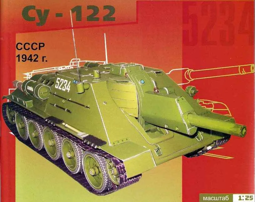
 TANK SU-122. Scale model 1:25.
Self-propelled gun SU-122 was developed in November 1942, the design Bureau of UZTM under supervision of L. I. Gorlitskiy. Leading engineer of the car was N. In. Kurin. A sample of the plant (factory designation I-35) was made on November 30, 1942 After the factory test, in the first half of December of the same year self-propelled unit has passed the state tests Gorokhovetsky Anope. On the arms were adopted on 5 December 1942 the Serial production started in December 1942 and lasted until August 1943 and All were released 638 self-propelled guns.
Self-propelled gun SU-122 was created on the basis of average tank T-34 and belonged to the type of a fully armoured self-propelled. The car was intended to destroy fortifications, destroy gun emplacements and enemy tanks. Armored cockpit was in the front of the case. The crew consisted of five people. The landing crew was made through a rectangular hatch, skryvavsheysya armor hinged cover located in the roof of the wheelhouse. The driver’s hatch in front of the compartment left of the gun was only meant for review. The hatch cover was installed one periscope observation instrument. On the roof of the car had a fixed observation cupola, the sides of which were made of a special glass window akrivastina armor covers. The tower was installed panorama of Hertz. In addition, for observation of the battlefield was used mirrored the observation devices installed in the front, right and feed sheets of armor cutting and commanding the panorama of PTK on the roof of the wheelhouse. Removal of powder gases from the crew compartment was carried out using exhaust fan. During the serial production machines, the latest release was installed an additional fan.
 The main weapon was 122 mm divisional howitzer M-30 model of 1938 with a piston valve and a barrel length of 22.7 caliber. The gun was mounted on a pedestal, supported by a transverse beam. Range direct fire was 3600 m, maximum – 8000 m. the Rate of fire is 2 RDS./min. Ammunition howitzers consisted of 40 armor-piercing and high-explosive shots separately-tubular loader. A shrapnel projectile with the weight of 21.76 kg had an initial speed of 515 m/s. Additionally, in the fighting compartment fit two 7.62-mm submachine gun PPSH with ammunition 1491 cartridge (21 drive), and 20 hand grenades f-1.
The armor protection of cannon-proof. The hull and deckhouse of welded, made of rolled armor plates with a thickness 15,20,40 and 45 mm, arranged with different angles of inclination.
The bottom of the machine was made of four armor plates connected by a butt-welded seams and reinforced linings. In the bottom was made three hatches with armoured covers: front manhole (in the fighting compartment), the average under engine (to access the oil pump and water pump) and back – to drain the oil from the transmission. In addition, there were five holes with plugs to drain the oil and fuel tanks, and eight rectangular cut-outs, four on each side, for mounting of suspension rollers.
Powerplant and transmission were borrowed from the medium tank T-34. In the rear part of the vehicle in the engine compartment mounted four-stroke twelve-cylinder V-shaped diesel V-2-34 500 HP (368 kW). Starting the engine is carried out by using the starter ST-700 with a capacity of 15 HP (11 kW) or compressed air from two air cylinders. The capacity of the main fuel tanks were 500 l-spare – 360 L. the range of the vehicle on the highway reached 600 km. In the course of serial production of the outer feed spare fuel tanks of rectangular shape was replaced by a cylindrical, placed on the sides in the aft part of the hull.
In the compartment located behind the engine compartment, housed the mechanical transmission, composed of: the main clutch, five-speed transmission, two friction clutches and two on-Board gear. As the rotation mechanism used friction clutches. Actuators control mechanical, with the use of serverplugin. Suspension setup was different from the chassis of the T-34 reinforced front suspension components. The electrical equipment of the machine was performed via one-wire diagram (emergency lighting – two-wire). The voltage was 24 and 12 V. the sources of electricity used four batteries 6СТЭ-128, connected in series-parallel with a total capacity of 256 A – h and the generator of GT-4563-relay-regulator, RRA-24Ф power of 1 kW and a voltage of 24 V. For the external radio in the car installed radio 9P for internal communication -tank intercom TTU-ZF.
The use of self-propelled guns for combat tanks were ineffective because of the low initial velocity of the projectile and a small flatness of its trajectory. The departure of the howitzer barrel was 700 mm, and in favor of the machine frame recoil devices of the gun worsened condition driving self-propelled.
 SPECIFICATIONS
Combat weight — 30900кг
The mass in running order kg -29600
The crew -5 people
Length 6960 mm
Width is 3000 mm
Height — 2150 mm
Clearance -400 mm
The length of tape in contact with the ground — 3720 mm
The width of the tracks — 550 mm
Specific ground pressure — 0.75 kg/cm2
Booking:
forehead body/angle — 45 mm/30°
Board/angle — 45 mm/90°
feed (tower)/tilt angle — 45 mm/45°
Armament — a 122 mm howitzer M-30 mod. 1938
Traverse of 10° left, 10° right
Elevation — -3° ; +25°
Ammunition — 40 rounds
Engine — In-2-34-M, 12-cylinder, 4-stroke, V-type diesel, liquid cooling
Engine power — 500 HP @ 1800 rpm
Number of gear 5 forward, 1 reverse
Fuel tank capacity — 420 HP (+270 HP – external tanks)
Fuel consumption is but the highway on 100 km — 155 L.
The speed on the highway — 55 km/h.
Cruising on the highway — 380 km
Overcoming obstacles:
rise — 30°
trench width — 2.8 m
stsci height — 0.9 m
fording depth — 0.9 m
Assembly instructions
 We will assemble a paper model of the average self-propelled SU-122. For the model we will need: cardboard 1 mm thick, 2 mm . When assembling I used microguru from the box from under the Shoe. A piece of cardboard with a thickness of 0.5-0.4 mm A4. Paper clips, it is better to buy a whole box of paperclips would need to build trucks. Staples will need 2 types of thick -50mm and normal. Floss handle shovel and saw. A piece of antenna cable with a length of 10-12cm. From it we do cable. The glue I used 3 types: nitrocellulose UHU that was used for the main work, stationery PVA, for gluing parts on cardboard, and finally super glue to strengthen the joints and fixing the axes of the rollers. Use for basic bonding PVA would not recommend this adhesive is water-based, after gluing the paper may warp. If You failed to find UHU, suitable conventional glue mark POINT.
Before you begin look carefully at the Assembly drawings, understand the sequence of parts installation. First try on the item in dry, look at how it is on the model, and then attach.
You should start with gluing the parts onto the cardboard. Items marked with *. glued on cardboard thickness 0.5-0.4 mm, items marked with # sign on cardboard with a thickness of 2mm. Items marked with ** on cardboard 2mm. Items marked with A are made from paper clips. All items are directly cut not worth it, can be confusing.
Immediately it should be noted that the model can be assembled in 2 variants for experienced collectors and beginners. The differences between these models on the appearance is negligible.
3: springs, tracks and bronenosca guns. All blade parts are cut first, and then with the reverse side of the first unit on office paper, and then cut off the excess.
Let’s get started.
 The Assembly will start with the bottom of the hull. Collect rigid frame of cardboard 2mm. Frame glued leaves of the bottom. Make sure to insert technological spacers when dry glue the body can lead.
Then begin the Assembly of springs and equalizers. In a variant of the simple Assembly and the springs are simulated. Then we collect the upper part of the body of cardboard thickness 0.5-0.7 mm, and pasted over its relevant parts. To collect the body together best pulled upper part into the lower, from the bow to the stern. I previously missed glue all the joints. Now we have to get ready the body of the model. Glue the wings and small things under them.
Next step put it on rollers. Rollers can be firmly fixed, and can be done moving, it will make installation of the tracks. Caterpillar we have 2 options – tape and teams of trucks. You decide which option is preferable. I tried both. Patterned caterpillars are harder to manufacture, but they look much more realistic.
Once assembled the chassis you can start assembling the mast and guns. Weapon of 2 hollow tubes. The instrument is installed on the armor plates. Again 2 options – collect from cardboard strips or glue from sweep. Appending from the scanner, do not forget to insert pre-2-3 inside the arc of the frame. After collecting the weapon set it on the carriage and fastened to the tower.
The next phase is the engine compartment. It is assembled from 4 parts. Grilles are assembled from thin copper wires are annealed above the fire – blackening and giving the cable the required flexibility. Mesh is made from a tea strainer. Securing the engine Bay move on to the smaller details. It is worth noting both the handles they are made from thick paper clips long is necessary.
A few tips: at present the market appeared a cardboard trucks made by laser cutting, you can use them. Fit is made for the T-34 width 535мм. Use watercolor pencil of the appropriate color to dye the ends of parts, I use a silver marker, it affects the appearance of the model appear “not” manufacturing defects.
We have to collect and secure the rope, a shovel, a saw and crowbars. I think the model. You will be pleased. Build a model of self-propelled installation SU-122 completed.
The materials to build a model TANK SU-122 (download)


