MILL INSTEAD OF THE PLOW

CUTTER INSTEAD OF A PLOW
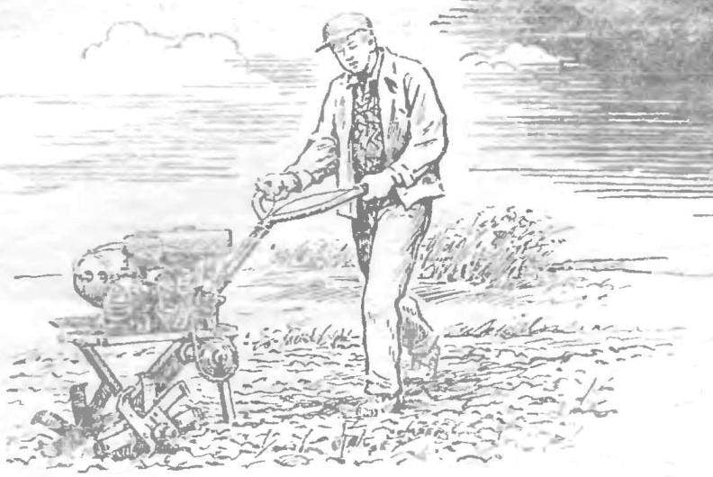
The tillers, was developed by Genrikh Alekseevich Kuznetsov from Moscow, is different from many homemade designs use instead of the plow cutters. Turning to the work shaft at the same time they cultivate the soil, serve as support elements and propulsion. Only a few minutes required to replace them on the wheels. Then the tillers are easily hung disc mower, dozer blade, trailer plow, mouldboard, the disc harrow, or a two-wheeled dump truck with a lifting capacity of 300 kg, are equipped with brakes. With the help of special tools you can handle a bed of strawberries, to transport logs.

The weight of walk-behind tractor with a full tank of fuel 72 kg (for comparison: MTZ-05 weighs 135 kg), three gear, speed 4-25 km/h. One hundred to plow with this machine for 12-15 minutes at a depth up to 230 mm.
 
The walking tractor is used the engine from scooter “Vyatka”, with air cooling, and forced that gives him the opportunity for a long time to work with maximum loads. Small alterations are to the clutch lever, the carburetor, the starting system of the engine to the transmission. So, for the convenience of the control clutch lever is deployed 180° from its stem at the base sawn off finger moved to the other side of the rod and welded on here Is allowed to put the clutch arm under the left arm and decrease the length of the transmitting cable.
 
Branch pipe carburetor connecting with the engine is deployed so that the carburetor was as low as possible in relation to the fuel tank: the fuel is supplied to it by gravity. Lever of kick starter is removed. The run is made using nylon cord wound on a homemade windup dural pulley Ø 120 mm. It is installed in the casing on the axis of the fan next to the last. For fixing the cord knot at its end inserted in the inclined groove on the flange of the pulley. In the box sector gear is welded to the control arm with a length more than 400 mm, which allows the speed of the switch, being directly over the handles of the carrier. When setting the sector back in place (on axis) after welding will note that the lever must be initially in a neutral position.
Walking tractor welded frame and is a quadrilateral (600×210 mm) of box section of rectangular cross section 27X25 2 mm; the rear part is closed area. Bottom departs from her box transmission with the clip on the main site, supported by emphasis. From the top to the frame are welded the motor bracket set bolt-on clamp holder PTO shaft with stand gas tank. The clamp is made of steel plate with a width of 23 and a thickness of 3 mm at each end drilled holes for M10 bolty. Engine mounting bracket from the two metal strips 32×4 mm is bent in a U-shaped profile; in the center of his neck 23Х10 mm for engine bolt; the other one is reinforcement — welded to it at the top with inner side.
 
Fig. 1. The walk-behind cutters
 
Fig. 1. The walk-behind cutters:
 
1 — engine, 2 — frame cultivator, 3 — the working shaft, 4 — knife cutter, 5 — wheel hub cutters, 6 — adjusting Board, 7 — bearing housing of the intermediate shaft 8, an intermediate shaft, 9 — star, 10 — PTO, 11 front of the gas tank with bracket, 12 — carrier 13 — the crutch 14 — tank 15 —crown-pulley, 16 — cover.
On the left two cutters are conventionally not shown.

 
Fig. 2. The frame of the cultivator Assembly
 
Fig. 2. The frame of the cultivator Assembly:
 
1 — frame, 2 — engine bracket 3 —housing unit rotation and lift carrier, 4 — heel, hitch, 5 — box transmission with the clip of the working shaft, 6 — frame, 7 — the-blank boxes.
 
Fig. 3. Stand gas tank with a hose clamp PTO
 
Fig. 3. Stand gas tank with a hose clamp PTO:
 
1 — front, 2 — lug mounting switch, 3 — cable bracket, 4 — clamp.

 
Fig. 4. Box transmission with the clip of the working shaft
 
Fig. 4. Box transmission with the output shaft holder:
 
1 — right cheek, 2 — clip, 3 — tape, 4 — nut adjustment Board intermediate shaft

 
Box transmission — welded. The basis of the metal strips 40X4 mm, cheeks somewhat more complex configuration with holes and cutouts with Its upper end it is welded to the corner of the frame, leaving her with a tilt angle of 35°. Therefore, cut the cheeks in different ways: from one side at an angle of 35°, the other at an angle of 53°. On and and hit the end of the box cut out a sector with a radius of 48 mm cage main shaft. In the right side (when viewed from the front of the tillers) drill three holes for M6 bolts for fixing Board adjusting shaft (with mount). In connection with necessity in the process of Assembly and operation to adjust the position of the output shaft and the chain tensioning provides for ellipse hole for the shaft.
 
In addition, there is welded a M10 Ganka square; in it is screwed the adjusting bolt the card with the lock nut of the Left cheek, unlike the right has a larger ellipse hole. This is necessary for putting the chain on the sprocket, tightening the bolts of the Board inside the box and allow lubrication and inspection sites. The hole closed with a lid for ten bolts M5. In short, the box is podranea part of the design on it are mounted the main parts of the transmission.
 
The transmission from the engine to the working body of the cultivator works as follows. The PTO shaft supplied sprocket number of teeth = 11. The intermediate shaft has two sprockets from Z=41 and Z = 11 bred in a box and is leading towards the working shaft, PA which is another with Z=15. Chain — two of them — taken in increments of 12.7 mm.
 
With the help of intermediate wool is a “movement” passed on it effort in the Central plane of the unit and reducing the number of revolutions. The shaft rotates in two bearings packaged in a metal housing, the Latter in turn is welded to the adjusting Board. Having three special holes for the mounting bolts on the box, the Board can move along it, adjusting the chain tension: fixed adjusting bolt of kills to build on his cheek Inner bearing is mounted in the housing so that partly enters the Central hole of the Board.
words about the build order of this node in the Beginning in the body is pressed on the outer bearing and inserted the shaft. Then put in place the inner bearing and at its remaining free portion is put on charge. Carefully, with breaks to prevent overheating the parts of the unit, it prepariruetsya to the housing and fixed by bolts on the box. Finally, the box upper ends of the cheek is welded to the frame. Please note that between the frame and sprocket PTO shaft with Z=41 is necessary to leave an air gap of 15 mm for the free running of the chain.
 
About the same going to a node of the main shaft, that is, start with pressing the bearing into the holder, insert the shaft, is fixed to the dowel sprocket, and install the second bearing. After the clip closed lids start to weld it with cheeks, and then carefully checking them for parallelism, welded to it the tape boxes. This order of operations on the Assembly to follow in order to separate the metal parts are not moved during welding and prevent their displacement relative to each other.
 
A few words about the chassis and working bodies. As already mentioned, the replacement cutters on the wheels — a matter of minutes, you just have to remove the hub cutter and put on to the hub wheels. Each of them consists of sleeve, flange and four digits: the connection between them is welded. The fingers are threaded under the nut length of the fixing disc wheels. In addition, bushings drilled hole Ø10 mm — the same are at the ends of the working shaft: the hub when the wheels are placed on the shaft, these openings are coordinated I inserted in them a cheque.
 
Fig. 5. Kinematics
 
Fig. 5. Kinematics:
 
1 — asterisk PTO shaft (Z = 11, Ø = 50 mm), 2 — star, intermediate shaft (Z = 41, Ø = 171 mm), 3 — asterisk intermediate shaft (Z = 11, Ø = 50 mm), 4 — star, and a working shaft (Z = 15, Ø = 66 mm).

 
Fig. 6. The hub of the wheel
 
Fig. 6. The hub of the wheel:
 
1 — flange, 2 — bolt М10Х25, 3 — Bush.

 
Fig. 7. Knife milling.
 
Fig. 7. Knife cutter.
 
Fig. 8. Of hub cutters
 
Fig. 8. The hub cutter:
 
1 — sleeve, 2 — flange

 
Hub mills is on the sleeve, two flange: internal and external, relative to one another rotated by 45°. Negi put on both sides of the flanges in pairs, parallel to each other, the “spike” in different directions, bolted M10. Just on the working shaft 16 is rotating milling cutters made of metal strips with a thickness of 5 mm. Hub cutters also are placed on the working shaft and fixed checks.
 
The Assembly of the motor-block it is better to, observing the following procedure. Frame with welded to it of the units and parts installed on the wheels and the crutch is fixed in a horizontal position. Placed on top of the engine so that the sprocket PTO shaft sprocket and the intermediate shaft are in the same vertical plane and between them and the frame could freely pass the chain of transmission. Therefore, the groove in the bracket stud under the engine mounts cut after a “fitting”. Then set the stand with the clamp (in a place), to put on both the chain and adjusted tension. In the primary transfer put the cover (box lid carefully close to the transmission does not hit the earth and dust), connect the tank, devices of the ignition system.
 
If you are working on wet soil viscous soil behind tractor wheels will slip, make a circular lugs, which if necessary can be put on wheels. To do this, wire Ø8—10 and a length of 1287 mm (for wheel motor scooter “Vyatka”) weld the two rings. Between them welded 12 Doug hooks, made in the form of segments of a metal strip (with a width of 15-20 and 3-5 mm) with an inner radius of 120 mm, as well as in any place of the ring — put the zip tie or bolt M8 with nut. Sawed off under the tie a small piece of wire, get the ability to adjust the tension of the rings грунт0зацепов to remove or, on the contrary, pinning them on the wheel.
 
G. KUZNETSOV, Moscow region

Recommend to read

  • RESCUE WET PAPERRESCUE WET PAPER
    Even with a good glass cutter is not always exactly separated cut piece of glass. However, if along the barely noticeable risks left by the carbide roller tool to make the tape wet paper...
  • STRENGTHEN THE VOICE OF THEIR HANDSSTRENGTHEN THE VOICE OF THEIR HANDS
    When I needed a megaphone, I became acquainted with the prices of Chinese industrial products: as it turned out, they cost from 1500 to 8000 rubles., and found that such a device can...