“Almost five years are a reader and subscriber of the journal “modelist-Konstruktor”. During this time, produced in any published developments in several homemade “for home, for family.” Would like to start welding-charging-starting device, a circuit diagram and description of which I had noticed in one of the rooms of the journal for this year, but deterred by the winding operation in the manufacture of powerful transformer, choke. And the installation of electronic control unit thyristors, I’m afraid not master. Whether it is at least a little to simplify the development of that interest me?”
The answer to this and other letters of request to the editor, is published below material
Indeed, to facilitate interested readers can develop, leaving her in a power transformer, the two “locomotive” T160 and the control unit thyristors. In the manufacture of the latter, by the way, it is easy to do without a winding operation, if transformers (and “silovik” and “impulselike”) get ready (the good, the domestic industry has already established mass production of good peers).
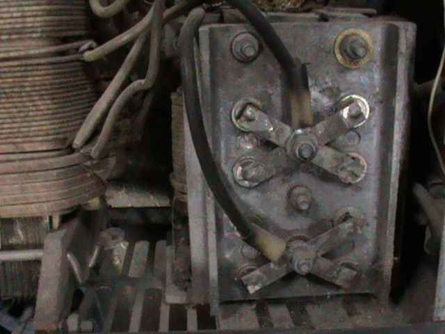
Since the secondary windings II-1 and II-2 of power transformer T1 with a separate, sequential connection is possible without any problems to a common point, and means instead of the diode-thyristor bridge to do only one pair of the above-mentioned T160. Moreover, using elementary switching jumpers (copper bars) in a homemade terminal strip (plate-insulator with bolts), it is easy to turn this basic unit in any of the variants of welding-charging-starting the unit, indeed indispensable “for home, for family,” especially for agriculture.

 “Almost five years are a reader and subscriber of the journal “modelist-Konstruktor”. During this time, produced in any published developments in several homemade “for home, for family.” Would like to start welding-charging-starting device, a circuit diagram and description of which I had noticed in one of the rooms of the journal for this year, but deterred by the winding operation in the manufacture of powerful transformer, choke. And the installation of electronic control unit thyristors, I’m afraid not master. Whether it is at least a little to simplify the development of that interest me?”