The best solution is to use an adapter with electrical isolation with electrical grid, toroidal power transformer (from the equipment on the low-voltage vacuum fluorescent displays). In addition to the network, and 40-V he has other windings: for chips, filament lamps and other purposes. As they say, there is an ideal opportunity for the creation of compact multifunctional devices, the output of which is easily variable voltage AC/DC (Fig. 1).
Such an adapter would be equally good for a soldering iron, and household radio equipment, musical bell housing, MICROTEL, car vacuum cleaner, instruments, electroplating and electrolysis. In fact, it is a universal low-voltage power supply, power enough even to charge the battery, if you connect it to the appropriate output jacks of this unit in series with the lamp filament or a current-limiting resistor. And the usual hot plate (220V, 600W) connected to a 40-volt sockets, a turn in the dryer or secure the heater — a kind of alternative to the Central heating.
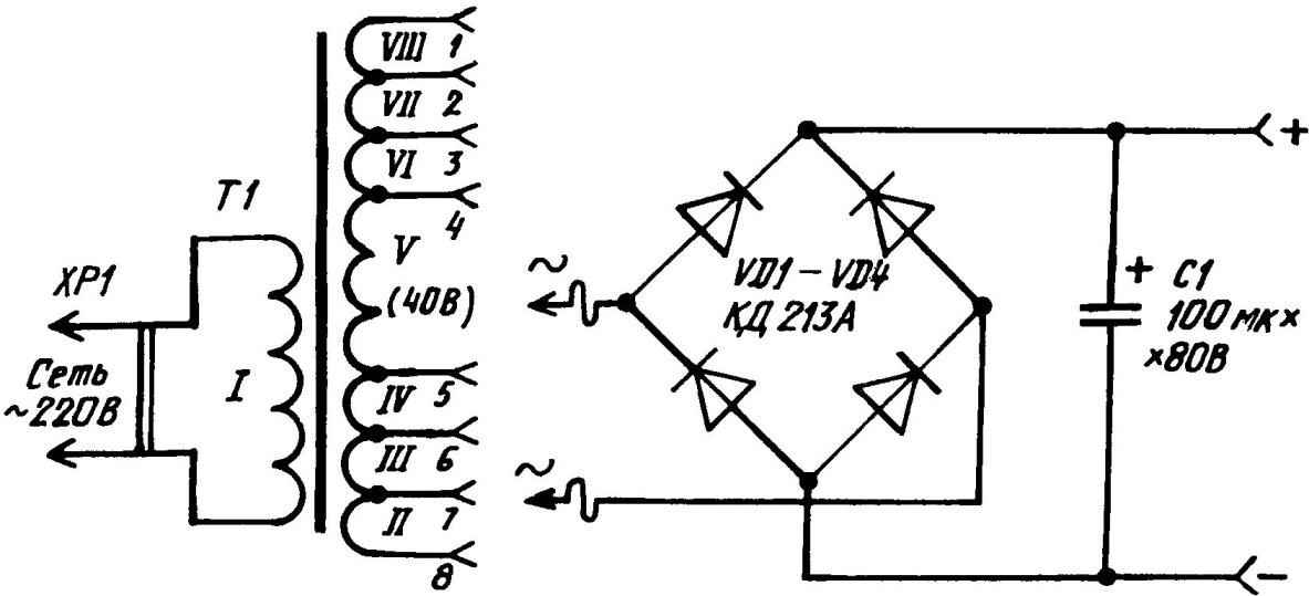
Fig. 1. A schematic circuit diagram of a power toroidal transformer from the equipment on the low-voltage vacuum fluorescent indicators, used as adapter for low-voltage soldering iron (with galvanic isolation from the mains), IO and as the basis of the multifunctional power source, comprising a self— made rectifier (the secondary winding of the transformer is conventionally shown for series-connected with each other)
The advantages of the proposed design of the adapter to a power source in comparison with the known analogues is the simplicity, and minimized the complexity of its manufacture. Perhaps the most difficult here— pinning pad switch, which uses an 8-pin tube panel with improvised plugs, toroidal transformer. Doing this operation (Fig. 2) use the tensioning screw, nuts, washers and textolite tube, for example, from a plastic bottle of shampoo.
Pre with transformer and remove the contact of a microplate, hotpaw from them and a bit of wire untwisted for this lacoccinelle tape wrapping, the integrity of which is immediately reduced To the terminals of the secondary windings put on 15-mm segments of PVC pipe, which, after desoldering conclusions in accordance with the circuit diagram (Fig. 1) pull on the radially curved contact petals lamp panel. Resting on the transformer, such elements are a kind of fasteners give additional rigidity to the entire structure.
If the secondary winding is small, the conclusions of the lamp panel to the end not involved in the case, and the output device is required to have a higher than 30-40 V, the voltage that can be domotai additional coils (or windings) of a wire of PEV-0,6. They can be run a thick wire. But in any case, it is necessary first, some bare transformer, unwinding protective tape wrapping of varnished cloth, and after winding the respective turns — it again to restore.
To calculate the required number of turns of the first flexible circuit wire 10-turn auxiliary (experimental) winding. When the transformer measure the voltage issued by it. Tenfold reducing this value to get the factor by which later divide the required voltage to determine the desired number of turns. Well, experimental coil already played its role are removed.
Insights network winding extend, podayva to them the cord. Stack rations wrap one or two layers of vinyl insulating tape. Then elongated insights network winding laid in a regular technological groove (it is located on side surface and intended for a typical installation of the lamp panel on the chassis — the circuit Board of electroradiologist), after which fix the output cord of the structure of clamping a rubber ring.
Next. On the transformer around a lamp panel is placed symmetrically welded to each other in the bridge rectifier valves (semiconductor diodes VD1 — VD4типаКД213А). The essential orientation of each body: metal side up, for best result the heat generated during operation. Connections AC voltage to the bridge rectifier segments carry out installation of wire mgshv-2, soldered to the two pipe plugs, which (when inserted in a socket 4, and 5 pad switch lamp panel) are electrically connected to the 40 volt winding V.
Rigid fixation of the rectifier bridge in its place is done by soldering the findings of the diodes to the tires of the rectified voltage positive/negative polarity adhered to the protective tape wrapped transformer (diametrically opposite portions) using segments of the varnished cloth or tape provided with appropriate markings (“+” or “-“). Each tire is a metal tape with a width of 5 mm cut of tinplate from a tin or sheet copper. The lower end serves as the output of the rectifier and a contact for connection to the load, compacted and protected chebrikova tube.
Fig. 2. Homemade multifunction power supply Assembly:
1 — bolt M5 nut; 2 — toroidal step-down transformer; 3 — the valve of the rectifier bridge (diode КД213А, 4 pieces); 4— wired AC voltage to the bridge rectifier (cut off the mounting wire mgshv-2, 2); 5— block switch (vacuum tube 8-pin panel); 6— the plug (cut the copper wire d3); 7 — textolite washer; 8 — the handle of the plug (cut chebrikova tube 8×2,07); 9 — bushing-shock absorber (the segment of PVC pipe 4. 4×0.5); 10 — clamping rubber ring; 11 — insulator-isolator (15-mm segment of PVC pipe strung on the contact petal lamp panel, 8pcs); 12— lead capacitor filter (cut off mounting wire mgshv-2,2 PCs); 13— filter capacitor (100 µf, 80); 14,15 — mounting tape (Scotch tape or glue varnished cloth, 3 pieces); 16 — bus DC voltage positive/negative polarity (5-mm strip of tin cut from cans, 2 PCs.); 17 — solder the output or a contact, compacted and protected chebrikova tube (2pcs); 18 — cap (from a plastic bottle of shampoo) or textolite plate-base; soldering the wires conventionally depicted with bold points;
Mnogoaktnye the filter capacitor of the rectifier is set in place (Fig. 2) on the basis of real needs. In particular, it is not mandatory, if the rectifier is the device will only be used to charge the battery. The mount with duct tape or all of the same varnished cloth, glued to the protective wrap the toroidal transformer.
Now a few words about a makeshift plug for the design. The base of each pin pin (cut off the bare copper wire with a diameter of 3 mm). The bottom end is rounded for a better entry into the socket lamp panel — pad switch, and the upper sharpened at an angle of 45° to the axis (here, solder the wire connections of the alternating current or load). The handle of the plug is tightly tensioned in a heated condition chebrikova cut tube having an outer diameter To 8 mm. soldered to the contact pin wire long served, not paralamas at the exit point of the arm, it is provided with a bushing-shock absorber. This is the segment of PVC pipe 4. 4×0. 5 mm, top incoming tight in the plug.
Switching the AC voltage supplied to the rectifier bridge to the load or directly to the load, is carried out by inserting the plugs in the different sockets lamp panel. To connect to the rectifier bus using the “+” and “-“. Acceptable here and soldering and plug-in connections with all known uncomplicated devices of the type “crocodile”. If the power load is small, then fit above plugs. Should the density of the crimping contact pin to the bus cuts will provide “ubiquitous and sepomaia” chebrikova tube.
SOLONIN, G. K o n o t o n, Ukraine
Recommend to read DUST AND DIRT Before painting the ceiling during the repair of the apartment it is usually carefully cleaned of previous coatings, and all around, usually covered that off. To avoid unnecessary dirt... THE WING ALONG THE FUSELAGE A distinctive feature of this model of rocket plane is turning the wing. It is set along the fuselage, which eliminates any possibility of the appearance of the spiral during takeoff. ...

 For feeding low-voltage soldering iron from a household outlet uses simple adapters, which are, as a rule, the quenching capacitance (capacitor for a specific value). However, the use of such a device for installation of equipment with microprocessors, field-effect transistors and other electronic components afraid of static electricity is undesirable. Too high risk of breakdown due to the direct connection of the heating element with electricity of high voltage. Need galvanic isolation. For example, in the form of a step-down transformer.