 Playing the electric guitar that uses the effect of “wah”, artist often have to press a pedal of a special electronic device. This often distracts the attention of the guitarist. In the console, the description of which we offer today, control the “wah” is made automatically from the signal of an electric guitar — like playing solos and chords. The device can be used with the pedal “wah”, in which alteration of the timbre is a variable resistor.
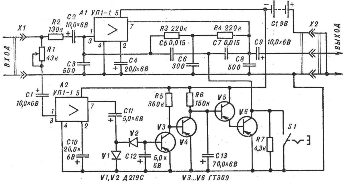
SCHEMATIC DIAGRAM
The actual “wah” is a conventional bass amplifier with feedback through a tunable T-bridge.
The signal from the guitar goes to pre-enhance fir, assembled on the block УП1-1 (A2), rectified by the diodes V1, V2 and is supplied to the transistor V3 (minus the base). He opened and V4 is closed; the capacitor C13 begins to charge through resistor R6. On the basis of the composite transistor V5, V6 gradually increasing negative voltage and then slowly changes the resistance in the area, “emitter — collector” V6. The result is a smooth reconstruction of the T-bridge and changing the timbre of the output signal. When the performer touches the strings or the picks when you play a chord let your fingers pressed against the strings, their vibrations will cease and the transistor V3 is closed and V4 open. The capacitor C13 will be quickly discharged through the open transistor V4, and composite transistor V5, V6 are closed.
The process is repeated with the resumption of the signal. The rate of change of the timbre Depends on the capacitance of the capacitor C13.
THE DESIGN AND DETAILS
The console is assembled in a housing made of polystyrene, covered with the inner side copper foil.
Details of “wah” except the battery power button S1, the connectors X1 and x2, assembled on the PCB of foil Micarta (Fig. 2). Two screws it is fastened to the housing.
Electrolytic condensers — K50-6 (C13 is selected in the range of 40-100 UF). Capacitors C3, C6, C8 — PM-1, C5, C7 — KLS-1. Resistors — all-0,125.

Fig. 1. Schematic diagram of the automatic “wah”
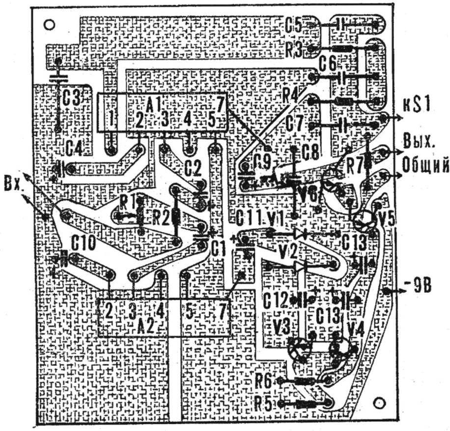
Fig. 2. Printed circuit Board console location details
As V1 and V2 can be any point of the diodes, for example D2, D9. In the diagram, the consoles work in almost any HF and LF transistors with In ≥50, but for the PCB to fit the transistors with a small diameter (ГТ309, ГТ108, ГТ322).
S1 — push button switch from the table lamps.
To console you can do the pedal, if the resistor R7 to take AC. In this case, the switch S1 is transferred to the input circuit A2. If the prefix you want to use ready-made “wah” is only part of the diagram for A2 and V3—V6. Input A2 is connected to the input of “wah”, and collector V6 with its variable resistor of the pedal.
The ESTABLISHMENT
By connecting the base of transistor V4 from “common wire”, the selection value of the resistor R6 set the voltage on the base of V5 is equal to 0.5 V. Then, the base V4 from the “common wire” is disconnected and the selection of the resistor R2 make the “wah” was working while playing chords and solos with a pinch each string.
Recommend to read
 AQUARIUM UNDER CONTROL
Aquarists usually determine the turbidity of the water in the aquarium, visual manner ("eye"), and beginners don't change it until then, until it is radiating the smell. However, with... OUTFIT FOR LIGHT
Perhaps the desire to dress up the light source comes from the primitive worship of the miracle of fire. Even the torch could just be stuck in a split stick, and you can revive the...
