 In the old days, when required to perform switching in the electric circuits when the voltage rises to a certain threshold, resorted to the use of polarized electromagnetic relay. However, the substantial size and weight, lack of reliability of the kinematics and contact pairs severely limited the use of these devices. Now in their place came a miniature non-contact thingies called discs. This four-layer semiconductor diodes whose structure is like a two transistor: p-n-p and n-p-n type, with the base of one is connected to the collector of the second, forming the internal positive feedback (Fig. 1).
While applied to the dynistor voltage Uo is small, both transistors are locked. As a result, the total resistance of the device is of the order of hundreds of ohms. However, when a voltage slightly larger than Uо, increased microflow from the collector of one transistor vtca in the second database, opens it.
A forced increase in the collector current of the second transistor strongly influences database first, also opening it. This growing avalanche process leads to a complete release of all transistor pairs, and dynistor switches to the conducting state (that is, its resistance drops to a fraction of an Ohm).
A clear illustration of the volt-ampere characteristic of the dynistor. Immediately drew the attention of the rising branch AB, which characterizes the voltage of Ies, which the device can withstand without losing the closed state. It corresponds to the normalized leakage current of Ies.
It is seen that with increasing voltage dynistor to the threshold level (Uвкл) operating point “slides” according to the plot of the BW characteristics to the conducting state (cool going up the line VG), where the current becomes maximum, equal to the Ioc. It confined the permissible heating limit the resistance of the external resistor.
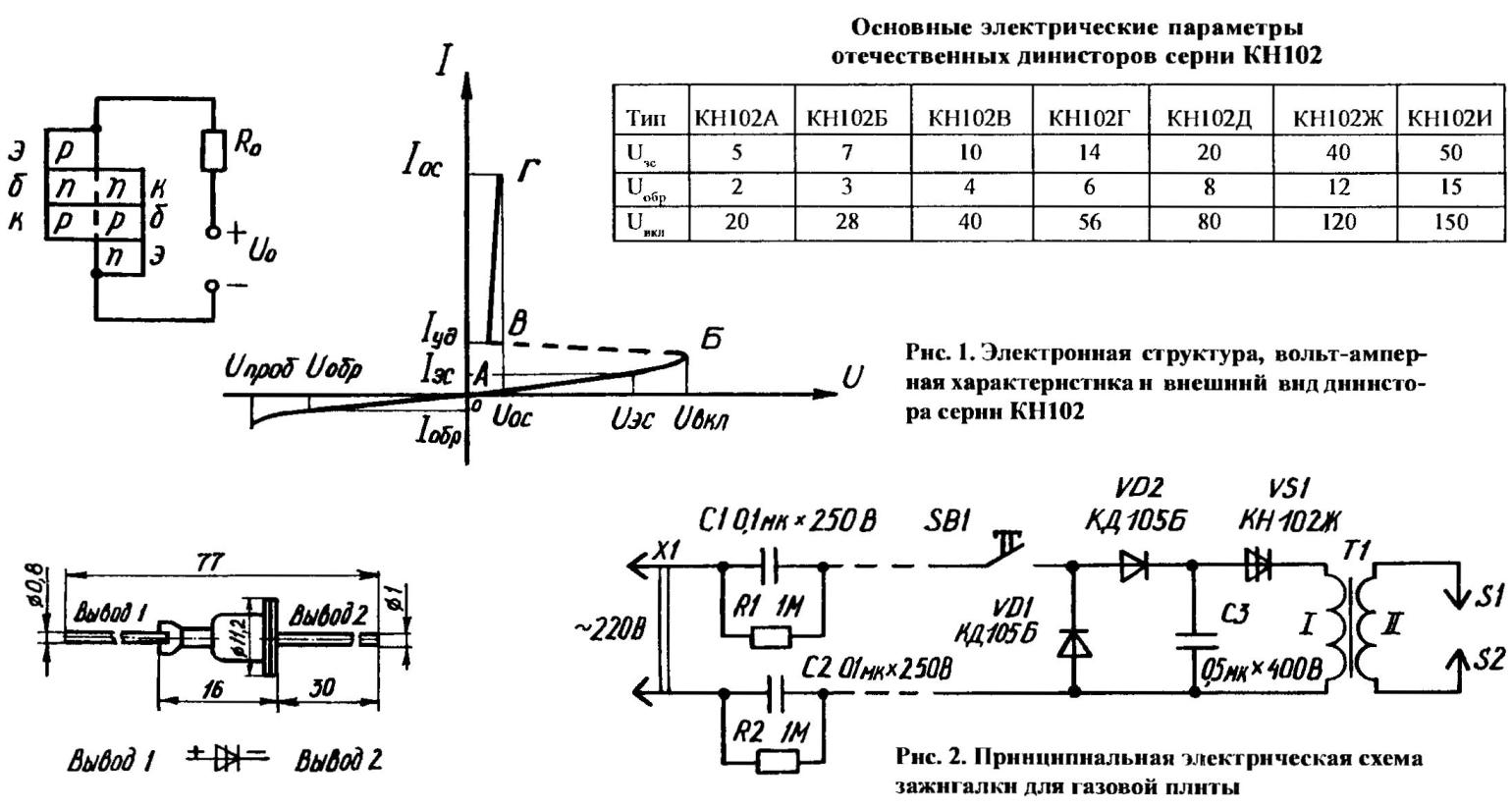
An important parameter in the dynistor is a minimum direct holding current of Jude (point b), below which there is self-termination device. The main technical characteristics when you change the polarity, of course, also include reverse voltage and current Uо6р Iobr. For domestic discs the most common characteristic of the series КН102: IOS 200 mA, 1.5 V IOS, Jude of 0.1—15 mA, the Institute of 0.15 mA,0.5 mA Iobr. Are represented by letters modifications of these devices differ only in the values of Ies, Uобр, Uвкл (see table). Not superfluous to know that in reality the figure Uвкл has spread, the lower limit of which about half are usually published standard passport data.
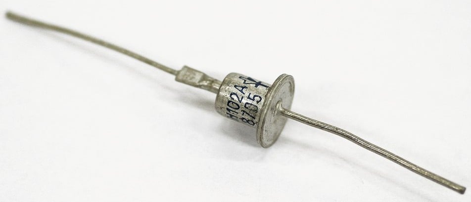
From the above it is clear that in order to translate the dynistor is in its off position, it is necessary to temporarily stop its current, to either reduce (in comparison with table-valued FTI) the current flowing through it. The configuration and dimensions of all members of the series КН102 (Fig. 1) the same rectifier diodes D226.
Based on the discs you can collect a variety of devices, from low-multivibrators and triggers to complex designs intended for experienced radio Amateurs. The following development is aimed primarily at beginners homebrew. This is needed in the home (especially if home or cottage gasified) electronic lighter.
As can be seen from the circuit diagram (Fig. 2), the recommended device consists of a noise filter C1R1C2R2 included the SB1 doggedly rectifier with a storage capacitor C3, the dynistor VS1, a pulse transformer T1 and the coaxial element of the ignition. Working in the so-called doubling mode, the rectifier charges from household lighting network a storage capacitor. And when the voltage on C3 reaches the level Uвкл dynistor VS1, the latter passes into the conducting state. A storage capacitor is immediately discharged to the primary winding I of the pulse transformer T1. Accordingly, in the secondary winding II is induced by high-voltage pulse, and between the coaxial electrodes S1, S2 spark breakdown occurs, igniting the gas from the burner.
The magnetic core of the pulse transformer is a ferrite rod with a diameter of 8 mm and a length of about 60 mm. Grade of ferrite with permeability of 400. First, a magnetic core wrapped with two layers of electrical tape. Then place the secondary winding, which consists of 1,800 turns of wire ПЭВ2-0,08. This is followed by two new layers of tape, and have them put the primary winding (ten turns of wire ПЭВ2-0,5) the ignition Element is a metal tube (electrode S1) with a diameter of 8 mm with through cuts which is coaxial segment of a knitting needle (electrode S2). The coaxiality is provided by two washers-inserts from flame-retardant dielectric
Having gained experience in the manufacture of electronic lighters, you can move on to more complex schemes where the dynistor plays an equally important role. For example, in the device (Fig. 3) allowing time to notice the weakening of the insulation, say, refrigerator, washing machine or any other household appliance. Included between the metal casing of the machinery used and the “ground”, which may be, for example, a steel pipe, it is timely to signal the appearance of undesirable 30 In the satellite’s aging electrical equipment.
The specified voltage level is not accidental. He is recognized as more safe for humans, but sufficient to judge about the troubles with the insulation and the desirability of timely repair. So when the body controlled home appliances appears 30, the dynistor VS1 devices are triggered, quickly discharging the capacitor C1 to the resistor R2. The resulting power surge briefly opens the transistor VT1 (КТ3107А), in the collector circuit of which is led NO red glow (АЛ307Б).
Since controlled AC voltage, upon the scheme becoming through the diode VD1 (КД105Б) half-wave rectified, so far after the discharge of the capacitor C1 (20 µf, 100 V) current through the dynistor КН102Б stops. But will start another charge cycle C1.
The foregoing process is repeated cyclically with the frequency of the signal flashes at about 1 Hz. Chain SB1R4 is introduced to check the health of batteries (type 3R12) by the forced unlocking of the transistor.
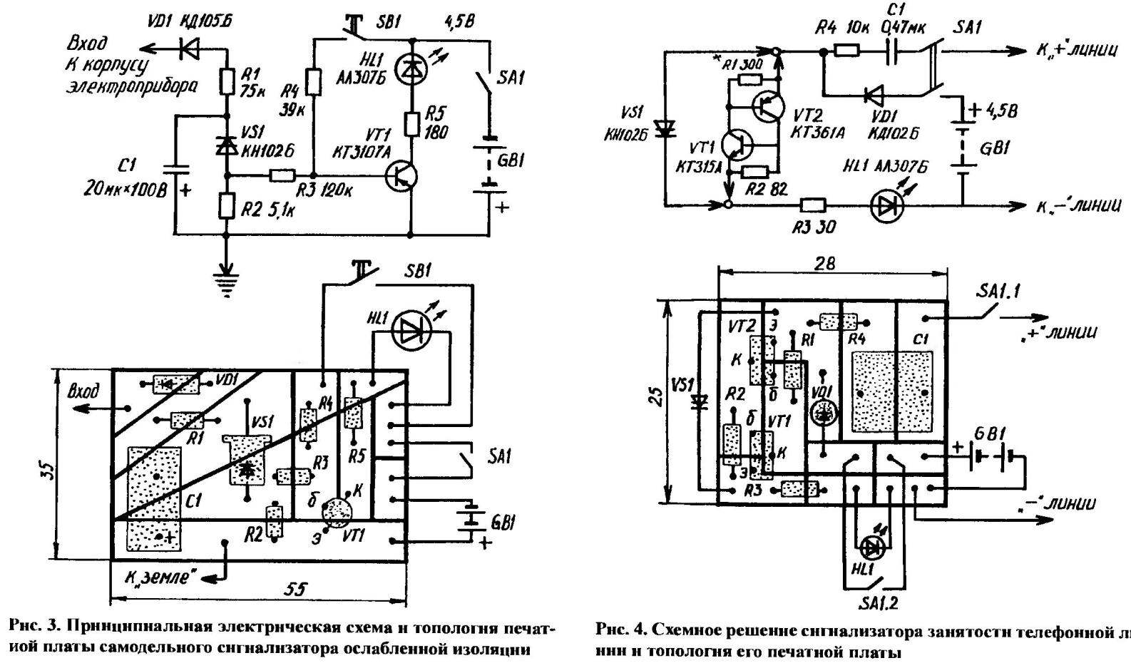
The package of the device, in addition to the aforementioned electronic components, consists of the MLT-0,5 (R1) and MLT-0,25 (other resistors), capacitor K50-29, button SPST on and microtubles (for example, from the old pocket receiver). Most of them are placed on a circuit Board from a one-sided foil 1.5 mm thick plastic. configuration Required pseudopath conductors is achieved by cutting the insulating grooves in the conductive layer.
And here is a homemade design for those who are forced to use a paired mobile phone. Its worth make sure when you call and the line is, say, busy excessively talkative neighbor. To quickly obtain reliable information about what line was released without picking up the handset on the telephone, assisted by the automatic detector is assembled according to the circuit diagram (Fig. 4).
The fact that steady when the line voltage on the input to a locked device is zero, but increases to about 40, when the line is released. It reacts dynistor VS1, attached to the “positive” wire of the line through the chain C1R4, the electrical parameters which is similar to the circuit of a phone call.
Jump line voltage is converted through the capacitor C1 in a single pulse, is able to briefly unlock the dynistor. As time this condition is fixed the current that will flow from the battery through and VS1 GB1 HL1. The result — smooth led lights — an invitation to pick up the device on and off does not need more than the detector.
The role of the diode VD1 is not to concede to the battery a relatively high voltage pulse from the line. If there is no suitable dynistor, it can replace analogue, assembled on the transistors VT1 and VT2, shown in the circuit diagram in the neighborhood of VS1.
Fabricate the circuit Board from foil Micarta or textolite dimensions 28x25x1,5 mm, I think, will not make special difficulties. A capacitor K73-9 required capacity, resistors MLT-0,25 desired values, a galvanic battery 3R12… in the presence inside the body of the phone is sufficient space charge with mounted thereon the electronic components can be placed in the machine, moving outward, and the led head microtuber. Well, as a power supply to use a battery made of three small cells type R03 or miniature SC-18.
P. YURYEV
Recommend to read
 INSTEAD OF WATERCOLORS
Do not rush to throw away the plastic packaging from used water-colour paints. It can be used for storage of small parts. L. MALAMUZH, g. Zolotonosha ALL FOUR ARE LEADING
The all-terrain vehicle is made according to a design that has proven itself well on the Kirovets tractor. It has the same “breakable” frame and drive on both axles. What does this give?...
