Judging by the pace, which is professional equipment in a recently available class gliders A1 soon and these “school” paritel can be divided into two distantly spaced from each other level. One, the elite, will be designed for construction and use at competitions of the international scale (accordingly to deal with such a technique will be able to a few units). The second mass, having no hopes for achieving elite results, and therefore, remaining on frankly mediocre level.
That prospect, of course, are not happy. But the published drawings of models, escaping forward, to the “adult” technique for circuit decisions, technologies used supermaterials and complexity of manufacture. Not always the chosen way to improve justified and engineering literate. However, the trend has been. And in the end it will bring the results of every kind, not to mention the increase in flight properties.
However… here is the amendment. All would be well if there were not one, sharply distinct “branch of” design “school” of gliders proposed by the magazine “modelist-Konstruktor” a few years ago. First publication in 1989, judging by the small number of responses, was among modelers as ordinary, though in the proposed design was already provided a very promising solution. But the following article… After its publication in the “M-K” № 1 for 1990 came a lot of letters as “the outrage of professional development and the impossibility of creating such technology in General”, and congratulations to the author and publisher. Wide response is clear: new types of models had invaded a pure sports classes and therefore attracted attention not only as “uchebok”. It is important that the design principles and the use of simple materials in many respects differed from the traditional methods of creating gliders.
What’s next? During the two-year “quiet” sorpresa new technology has made another step in its development. Moreover, it’s a proven and competitions. Suffice it to say that models of this type won the championship of the Moscow region; the same equipment the guys became winners of the Moscow championship. I must admit that they are in class A1 boys are not the worst models, and therefore prizes say a lot. But this — read more in the article itself. How and what changes have been very promising development…
Before I talk about the new model class A1, it is necessary to warn to the end to assess the design, understand all the details and features of the schema will fail if you additionally will meet No. 5’90 “M-K”. Some of the information in some degree duplicating the previous article, not included in the proposed today because of the limited amount of journal publications. So here you will not find any detailed comparative strength analysis of the wing, nor regarding the formation of the popularity of the classes of small gliders in the international arena.
So the new technique. The basic material for its creation was the lime of different density. For most parts found pure white variety with high density and strength, respectively. Of course, this is not the only suitable material. Probably higher prochnostnye features would spruce (which comes to musical instruments and what can be purchased in Moscow near the metro “Botanical garden” in the store when the company “Lira”) or a grained pine high quality.
The main (and almost only) binder for Assembly of the frame was epoxy resin grade K-153. Replace it with nitrogly generally meaningless, as the power circuit was originally designed for the lack of extended seams in favor of several separate, but very high quality fused nodes. At the same time To-153 — one of the few resins which not only has a good combination of strength and elasticity (for wood type basswood gives the equi-strength joints), but also with long-lasting thickening and low viscosity allows bonding method of loading.
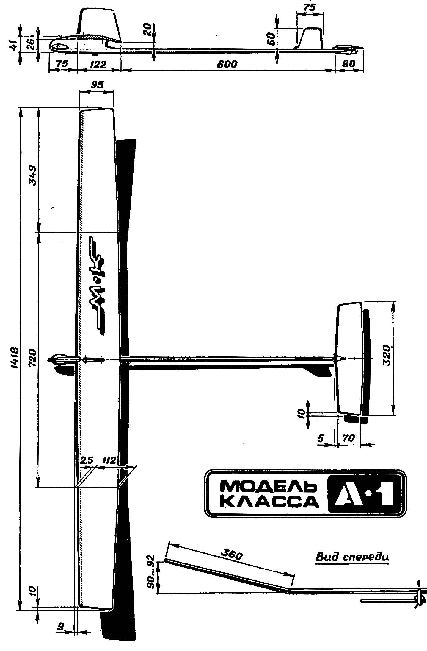
The principal dimensions of the model glider.
Almost all components on the model were first assembled on the pins and the clips dry. Then use the “brush” (a thin needle is clogged the end of the rails) on the joints was applied the resin. Prolonged gelling time of the binder ensures reliable absorption of the resin over the entire area of the joint. The excess is removed with a wire ring (head sewing pins) after some time, when the resin acquires the density of honey. Now, if during growth the viscosity of the resin from time to time to turn the frame on all joints, a uniform adhesive fillet of constant radius.
In total, this technology stitching is very time-consuming and takes a lot of time (especially considering the continuous control up to the full gelation). However, if you acquire experience, at once manages to shed almost all of the joints, for example, the center section of the wing! After all, in comparison with conventional designs for the new technology these joints much less.
But most importantly, the reception of the cast resin allows to achieve simply amazing strength qualities. The technology is versatile and suitable for all model elements. Even the stabilizer, where savings of fractions of a gram, is assembled by the proposed method. In spite of the fillets at all joints with radius of about 1.5 mm, it was found that in the amount of ten the butt of the frame units of the stabilizer added only 0.3—0.4 g. In this case the strength is such that the tail gets really everlasting in any treatment model.
Pre-pasting joint surfaces required only for large areas. The glider is only needed at the point of joining of the tail boom and forward fuselage. By the way, in these compounds, the resin should be applied abundantly, to pour a “cushion” of glue on the connected seam. This will eliminate neproblem and loss of strength associated with the absorption of the epoxy into the pores of the wood. The excess resin after curing is removed in the finishing operation details.
The fuselage. The design of this element of the model is so simple that it requires no explanation. Therefore, it is possible to stop only on technological features. After assembling the beams, the bow and cradle the wing serverlists holes for screws. Drilling depth should exceed the depth of the planting screws 2-3 mm, and the diameter of the drill to be equal to 0.5 of the cross section of the neck of the fastener. The screws should be carefully selected, as most have rough ragged cuts. Socket pre-formed by screwing the screws. Then they filled svezhenakleennyh resin and after exposure for 15-20 min, when the bulk of the resin will go into the pores of the wood, the screws are screwed themselves. For protection from gluing them to protect the simple pasting of a stearin candle is enough to make the metal parts easily twisted.
Pin-axle for mounting the keel to the beam end it is better to not seal the drilled hole and punctured. The fact is that when you puncture with a sharp awl layers of wood just parted, and a beam remains the same-strong, with no impairments. The surrounding areas you can additionally wrap a thin nylon thread with the resin.
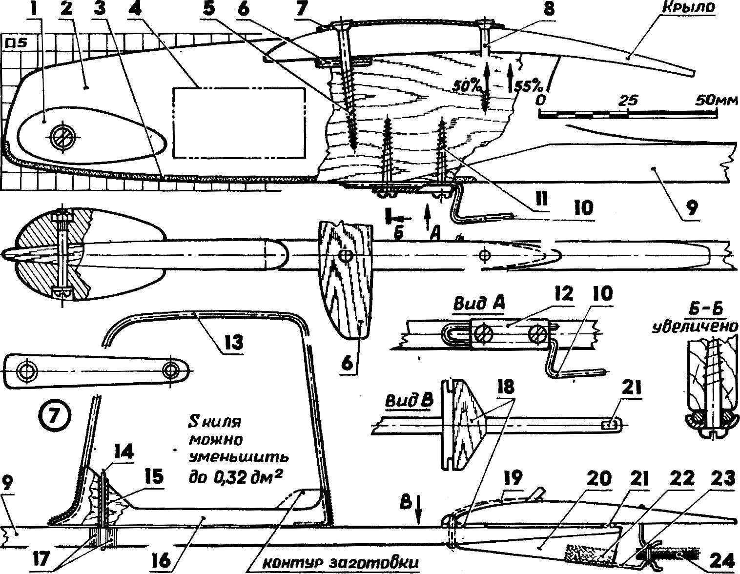
Fuselage:
1 — bow-boot (lead; fastened with M3 screw, M3 nut pressed in the right part of the download), 2 — nose portion (lime, medium density 8 mm thick), 3 — strip (a thin fiberglass or a wear-resistant film of the “Solarfilm”), 4 — the location of the clock mechanism (option), 5 — front-screw 3X35 mm, 6 — tool tray (plywood 2.5 mm), 7 — pad (made of anodized aluminum 1 mm), 8 — rear screw (2,5X25 mm) 9 — tail boom (thick lip section 8H11 mm; from the back edge of the wing to the front edge of the stabilizer of cross-section to reduce the wedge to 4X5 mm), 10 — tow hook (OVS wire Ø 2.0 mm), 11 — screw fixing hook 2,5X25 mm (2 PCs), 12 — pad (steel 0,5 mm), 13 — outline of the keel (aluminum knitting needle Ø 2 mm, after molding, the ends should be degreased and wrap a thin cotton thread), a 14 — axis attachment of the keel (OVS wire Ø 1 mm; to seal the plot to dash off and degrease; to put in a pierced hole in a beam), 15 — tube (medical needle), a 16 — base (lime 2.5 mm; workpiece thickness of 4 mm is processed after Assembly), 17 — winding (fine thread), 18 — tool insert of the stabilizer (plywood 1.2 mm), 19 — tape attachment (the ring is from the fingertip), 20 — keel (Linden 1 mm), 21 — lined (lime), 22 — fastening hook (nylon tape), 23 — hook wick (OVS wire Ø 0,8 mm), 24 — wick.
 Judging by the pace, which is professional equipment in a recently available class gliders A1 soon and these “school” paritel can be divided into two distantly spaced from each other level. One, the elite, will be designed for construction and use at competitions of the international scale (accordingly to deal with such a technique will be able to a few units). The second mass, having no hopes for achieving elite results, and therefore, remaining on frankly mediocre level.