Induction coil, in the last century invented Rumkorem, and is now used in experiments in physics. But now it is not fully satisfy the requirements of physical experiment creates interference, does not regulate the high voltage. consumes battery power, and feed the coil directly from the mains AC is impossible. We offer you to equip physical classrooms modernized version of the instrument developed on the basis of electronics.
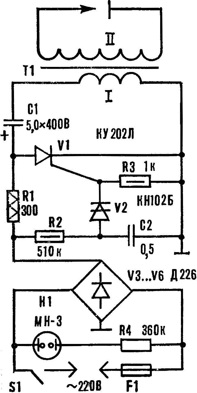
Ruhmkorff coil (Fig. 1) consists of three components: the rectifier is assembled according to a bridge circuit of diodes V3—V6, e-switch on the dynistor and the SCR V2 V1 and the high voltage transformer T1. The device uses the principle of capacitor-switching of the SCR voltage circuit and the primary winding of the induction transformer.
Fig. 1. Schematic diagram of the electronic gap.
When the device is included in the network AC voltage of 220V, a storage capacitor C1 through the resistor R1 and the primary winding of the transformer is charged up to the peak value of the rectified voltage of about 310 V. at the same time starts working as a relaxation oscillator of the electronic switch. At the moment when the voltage on the capacitor C2 becomes equal to the breakdown voltage of the dynistor V2 open. The current pulse in the circuit of the resistor R3 opens V1. Storage capacitor C1 is discharged via an SCR and the primary winding of the transformer T1. Its secondary winding is induced a high voltage pulse with a value of 40— 60 kV.
Fig. 2. The high voltage transformer.
At the time of discharge of the capacitor C2, the dynistor and the SCR is closed, the current in the primary winding of the transformer is terminated. Sequentially the process is repeated with a frequency of 5-10 Hz.
The parameters of the parts used in the device are not critical, but preferably, the values of the switching voltages at V1 and V2 was higher. The R1 resistor wire. As the transformer T1 used ignition coil car or motorcycle. From the spool and remove the plastic cover and the metal casing, is wound the primary winding. Frame for a length of 1.5 cm pull the core and its projecting area wear two little cheeks with a thickness of 1.5 mm, cut from an insulating material (Fig. 2). Between 90-100 wound turns of wire of PEV of 0,6—0,8.
Board with the mounted device is placed in a plastic box with approximate dimensions 240X240X50 mm. In its upper part mounted socket connected to high voltage, and the inserted pins of the arrester (see Fig. 3). Pins and borne arrester made of banana plugs and wire rods: one of them soldered metal disc Ø 30 mm. the shoulders of the arrester is installed in a metallic clutch, and fixed clamps.
Fig. 3. The appearance of a physical device.
Spark discharge at the collected unit should achieve a 30 mm. high voltage adjust in the range of 2-50 kV using Later.
V. CHERNYSHEVSKY, Kommunarsk, Voroshilovgrad region.
Recommend to read ON SAILING Those who live near the water, the boat is as necessary as for other bike or car. Of course, experienced shipbuilders-fans are unlikely to descend to the boat, we want to bring to your... “THE WINDMILL” FOR BAD WEATHER Thunderstorms, ice storms, hurricane winds frequently break the electricity settlements (sometimes up to several days). How to survive these days the villagers? You can buy petrol, but... 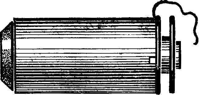
 Induction coil, in the last century invented Rumkorem, and is now used in experiments in physics. But now it is not fully satisfy the requirements of physical experiment creates interference, does not regulate the high voltage. consumes battery power, and feed the coil directly from the mains AC is impossible. We offer you to equip physical classrooms modernized version of the instrument developed on the basis of electronics.