
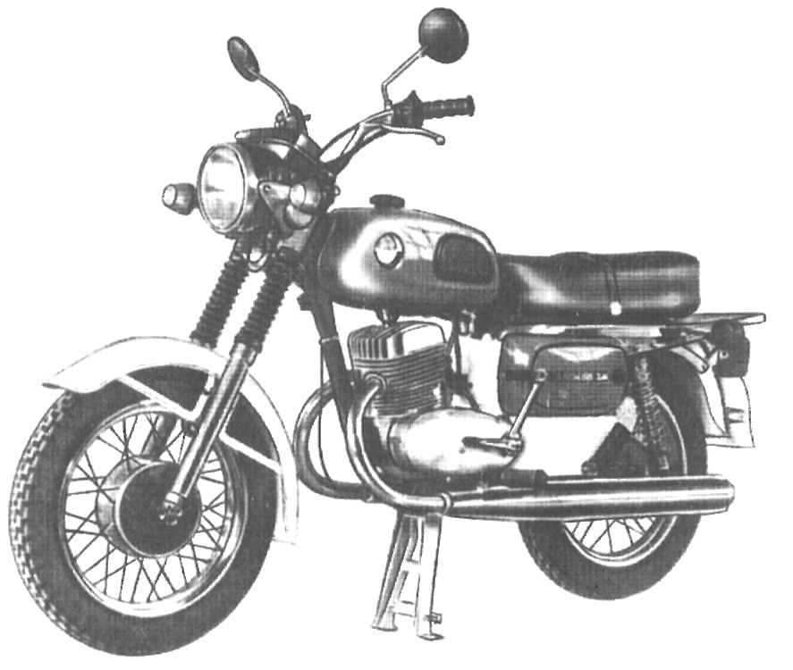
 More than two years have passed since then, as I have installed it on your motorcycle “IZH-Jupiter 4” contactless ignition on the basis of voskhodovskogo generator, switch 262 3734 and a homemade diode mixer (Fig. 1.). Making sure the reliable working of my creations, and colleagues conducted such an improvement to your motorcycles However there were questions like, “I drew on your chart — explain why me doesn’t work.”
Some common faults:
— no spark at all;
— motor runs well at idle, but fails at speeds higher than average;
— the motor starts good but runs mostly one cylinder, the second picks up occasionally, outbreaks are followed unevenly,
— there is no spark only with the installation of the scheme Property of “Sunrise” spark, when you replace the switch unit stabilizer (BCS) are similar, (251 3734 CAT 1-A) the fault disappears.
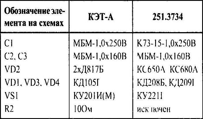
All these troubles point to a defect of the BCS. Consider the original block diagram (Fig. 2.). It is copied from block CAT 1 issue of the 1980-ies. In terms of switches, a Zener diode VD2 presented КС650 (or two cascaded Д817Б) of the Last execution of BCS — 251 3734, 3734 261, 262 3734 schematically do not differ. Only changed the appearance and type of some parts.
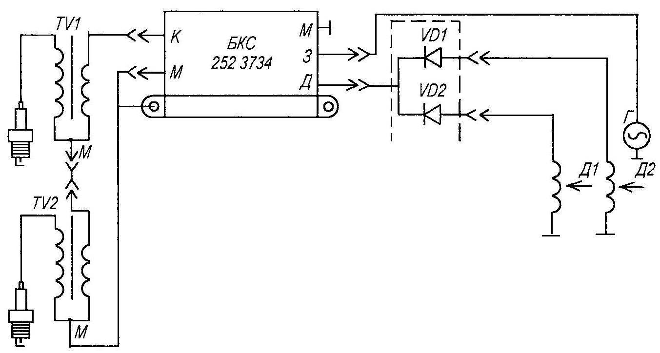
Fig. 1. Contactless ignition on the basis of voskhodovskogo generator, switch 262.3734 and a homemade diode mixer
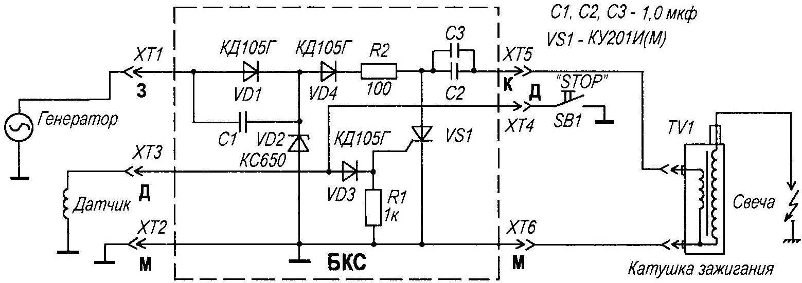
Fig. 2. A circuit diagram of a switch unit of the stabilizer (BCS) factory production
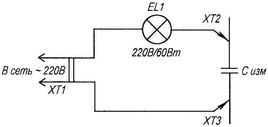
Fig. 3. Scheme checking of capacitors and SCRs for leaks
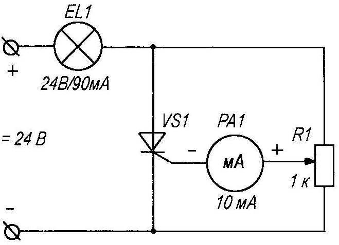
Fig. 4. Diagram of the device for the selection of a trinistor of VS1
The principle of operation of devices of the same capacitor C2 is charged from the high voltage winding of the generator circuit VD1, C1, VD2, VD4, R2. A positive voltage pulse of otdatsya through VD3 open SCR VS1, which discharges C2 to the winding of the ignition coil TV1, forming a spark at the spark F1. A VD2 Zener diode limits the voltage at С2VS1 at 130 — 160 V. However, the running switch, the voltmeter showed 194 In a clear strain, the influence of the variation of parameters of Zener diode I Want to mention an interesting detail — as applied C2 two capacitors of the type of MBM. These capacitors can operate in pulsed mode. Being a “self-healing”, they can easily tolerate a short-term surge. Places of breakdown of the plates fills the paraffin impregnation of the dielectric. Unfortunately, this does not go unnoticed — over time, the foil of the plates begins to resemble a sieve, the capacitance of the device decreases. The dielectric breakdown leads to the increase of conductivity and the appearance of leaks. Working in switch, the capacitor simply does not have time to accumulate charge during the time between two sensor pulses. That’s why normally operating “Voskhod” (“Minsk”) the unit is acting up in the scheme Property, where the frequency of impulses run twice.
Capacitor leakage is detected by a simple scheme (Fig. 3.). Compliance with safety measures (circuit electrically connected with home network) check the connected capacitor in the circuit. Light bulb-the led should not — the glow indicates the presence of leakage. Scan time 15 to 30 minutes (in cases of doubt — to 1 hour). Despite the somewhat barbarous method of testing, for the condenser it is practically safe. In the process of operation it is subjected to heavy loads. Thus, I have identified thirteen capacitors with an obvious leak, four of them in blocks, worked fine for single-cylinder engines, but sbivshy in the scheme Property. To replace the capacitors in CAT-1A is easy — the unit can be easily disassembled. The same replacement in the performance 252.3734 hard. To start, remove filling the housing a porous mass, provari the switch in boiling water for 15 — 20 minutes. Then gently “pull out” the filler with tweezers. Pulling on the connectors, remove the card and get access to the printed installation. You can, of course, replace the faulty unit of the same, but there is no guarantee that the new will soon also fails (reason see above), so I recommend to change the capacitors type K73-17 1,0 UF/ 400V (or even better 4×0,47мкФ/630V). Two capacitor normally located on the card. The sealing of the unit is performed by pouring it construction foam or cut to size plate rubber. Warn from the use of different autoerotica their active components will eventually destroy the copper traces of the Board. In order to ensure maximum reliability of the device “no alternative” option I believe metalloboranes type capacitors MBG, MBGP, MBGC (the letter G indicates the design of the device), designed for a voltage of 400 — 630 V. the Only problem in this case — dimensions. A possible compromise option in the schema for “Iz-u” value of C2 reduce to 1uf. This will provide guaranteed battery power for a half-revolution of the crankshaft.
The remaining elements of the device specific complaints usually do not cause. C1 (K73-15) is reliable enough. Diodes VD1, VD4 suggest to replace КД226Г (with yellow ring) VD3 almost “Neubauer”. It happens that SCR VS1 is replaced by its features (the engine begins to run in the opposite direction) — it is possible to remove and replace it КУ202Н or (even better) on Т122-20-10. Rarely fails КУ221Г (КУ240А1). Replacement SCR is associated with the selection of the minimum current control. This scheme ignition very sensitive to this parameter. I spend the selection by using the schema depicted in figure 4, Moving the R1 engine from the bottom up, note the milliammeter PA1 a current value of the opening of the investigated SCR VS1 on top of the glow lamp EL1. To use select the instances with the current I = 1 — 8mA. Unfortunately, there are SCRs with increased leakage current. Verification of this parameter is according to the scheme shown in figure 3. The glow lamp would indicate malfunction of the device.
Recovered so BKS are suitable for further use in the ignition system, both single-and two-cylinder motorcycle.
D. STORIES, Kashira
Recommend to read
 “WATER BEETLE” – A FISHERMAN’S BOAT
What is fishing without a boat? Especially on large bodies of water. Want to make an original, virtually silent floating craft? Then let's get down to business. Look at the picture. The... YOU TAKEOFF!
Training RC model airplane. This publication is for those who have sufficiently mastered the piloting cord model airplanes and thinking about the next step — creating the RC. You can, of...
