
 The inclusion of transformers on 400 Hz network, 220 V(50 Hz) using a ballast capacitor. If you look at the merits in diversity of industrial and self-made Amateur radio power supplies, it suggests the surprising conclusion. Basically they use the same (from a large item being sold) step-down transformers.
As is known, the transformation ratio depends on the resistance of the windings, electric current, power load connected to the secondary winding of the transformer and the applied voltage in the IP (the primary winding). Moreover, it is important that the frequency of the lighting network was equal to 50 Hz (with minor deviations). In the designation of the transformer frequency is indicated on their body.
In practice, the same transformer may give a different voltage at the secondary winding depending on the voltage on the primary winding.
The transformers operating in buck mode, the primary winding has resistance to an electric current much greater than the secondary (and subsequent, if any). In order to deal with the windings (when the unknown reference data or marking on the body is unreadable), it is recommended to check the resistance of the windings using an ohmmeter and the one that has maximum resistance, is connected to the network 220 V. Any hard criteria for the resistance of the primary (network) winding no, and it can be 100 Ohms and 1 kOhm — it depends on the power and purpose of the transformer. It is reasonable to note that to include directly in a network of 220 V AC transformer with a coil resistance up to 10 Ohm is dangerous. For this purpose, autotransformers (included between the voltage of 220 V and the experimental winding of the transformer) or ballast capacitors, which will be discussed below.
The hams will probably be useful to know what power transformers are popular among the electronic structures and have proven themselves on the positive side of safety and duration (in clock mode) efficient operation. In the table for example, given values for some common transformers, that the author repeatedly used in their electronic structures.
Except transformers designed for 50 Hz, there are others designed for other purposes, respectively. For example, filament transformers for a frequency of 400 Hz used in aircraft industry and specialized electronic devices. Ham radio should not be discounted, as such “inappropriate” transformers it is possible to make dozens of useful products such as voltage converters and power supplies with frequency 380… 1000 Hz at different load conditions (including maximum) of power.
Consider the widespread transformer TA1-220-400. It can be used as a buck in a lighting network 220 V 50 Hz as the basic element of the power supply. Maximum output current it is small, of the order of 70 mA, however, due to the relatively high output voltage (30 V) it is essential, for example, to power incandescent indicators (in particular, IV-21) and in several similar cases.
The figure is a circuit diagram of a power source, where the applied step-down transformer TA1-220-400.
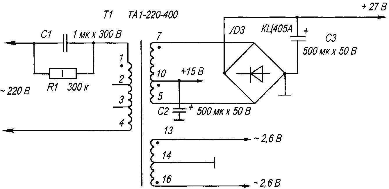
The electrical circuit of the transformer TA1-220-400 V 220 V 50 Hz
This scheme can successfully serve the hobbyist who decide to make their own low-power power supply with an output voltage of 2.5 V (AC) and 27 — 30 (DC).
Both voltages will be useful for testing a homemade original designs. For example, a voltage of 30 V (both AC and DC) it is appropriate to use in the laboratory Amateur radio operator with the call setup of the telephone apparatus with the function of caller ID (and not only). This signal will simulate a call with a phone line is much safer than the real signal from the telephone line with an amplitude twice as large. In addition, the output voltage is 2.5 V it is convenient to use for home power hours-alarm clocks with a voltage of 1.5…3 by passing it through a small rectifier circuit (then you won’t have to constantly buy batteries), as well as to supply the battery charger disc batteries and elements with the same nominal voltage.
The main circuit — do not reverse the connection of the windings of the transformer T1.
Operation of a transformer at 400 Hz 220 V virtually safe through the ballast capacitor C1 and shunt resistor R1 mounted in series with the primary winding of T1. Non-polar capacitor included in the circuit of alternating current, behaves like a resistance, but unlike the resistor is not absorbed dissipates power as heat. This allows to construct a compact (due to the miniature size of transformers on 400 Hz) power source, lightweight, and relatively inexpensive. The value of capacitive resistance of the capacitor can be determined by the formula: XC = 1/2пfС, where p — (PI), f (frequency) is expressed in Hz, C in farads. In the case where the load voltage does not exceed 30, it is also appropriate to use the formula: C = 3200хІн/IP. The capacity of the ballast capacitor in microfarads is determined, the IP — voltage network (220 V), I is the load current in circuit (A).
Thanks to the inclusion in this scheme, step-down transformer, the safety of using the recommended power source is greatly increased (relative transformerless source ceteris paribus).
Changes in the capacitance of the ballast capacitor C1 in this circuit can adjust the output voltage of the power source, which is very convenient. It’s also possible to include in a network 220 In and other transformers with low-voltage primary windings (not designed for voltage 220 V). The ballast capacitor is in this case selected so that at maximum load current the output voltage of the transformer maintained.
The ballast capacitor C1 in this circuit is used for a working voltage of at least 300V (for example, MGC-1, MGC-2, K73-11, K73-17 and similar).
Electrolytic capacitors C2 and C3 smooths the ripple voltage on the output of the rectifier is implemented using diode bridge VD3. The withdrawal from the middle secondary winding of the transformer TA1 -220-400 (pin 10) allows to obtain a constant (relative to the common wire) output voltage 15 V. If such a decision is not necessary, the connection of the secondary winding can be restricted to terminals 5 and 7 of transformer T1, diode bridge VD3 and capacitor C3.
For filament transformers (symbol TA, TN), intended for work in electric circuits with frequency of 400 Hz, it is possible to make the effective voltage converters for powering, for example, shavers, photoflash or low power fluorescent light. Moreover, the primary power source is the automobile (or other) battery with a current of at least 500 mA and a voltage of not less than 10 V. the Diagram of such transformers is described repeatedly in the literature.
Also indicated on the transformer circuit is also suitable ТН30-220-400, ТН32-220-400, ТН36-220-400, ТН60-220-400. In these cases, only changes the output of the transformer (respectively 30, 32, 36, or 60 watts) without schema changes. And transformers type ТН47-220-400, ТН48-220-400 will also need to specify their Pinout conclusions. Electrolytic capacitors C2, C3 of the type K50-24, K50-29 with an operating voltage of not less than 50 V. a fixed resistor R1 — type MLT-1 or similar. The diode bridge rectifier VD3 — type КЦ405А — КЦ405Е (or similar). It can also be replaced by four discrete diodes of the type Д220, КД105 (or similar) with any alphabetic index.
Power transformers for power supplies on 220V (some popular types of Amateur radio practice): ТН1-220-50; ТПП218-127/220-P; HS-2 (3,5,6); ТПП259-127/220-50; ТПП255-127/220-50; TS-10; e-255; TP60-17; ТПП277-127/220-50 (nom: network 2-9, jumper 3,7).
The secondary winding independent: 11-12 (14) 13-14 (10) 15-16 (6.3 V) 17-18, 19-20, 21-22 (2…3V); TP-112-5; ТПП217-127/220-50 (225,235,236,261); ТПП1204/220/12; ТП121-1; TS-100B (powerful); ТПК2-22; TP-321-5; TP8-4-220-50; TS-26-1 (conclusions of the windings and output voltage: 1-2 — 220 V, 3-4, 4-5 — 16 To, 6-7, 19 In 0.2 A, 8-9 — 5 V 0,3 A); TCE-110L (LM); TCE-110-312; TR-1-6/15; TCE-70 Uout (15…17); TP8-3 Uout(15…17V); TP20-17 Uout (15…17); TP45-1 Uout (15-17); ТП234; TCA-370; TS-370; ТПП232 analogue ТПП253.
A. KASHKAROV, St. Petersburg
Recommend to read
 THE FARM WILL FIT; SHOWCASE-BOOKCASE
The list of Moto - and electrophotonics that use rural residents, is growing steadily. Along with tractors, tillers, mills, kartoffelschalen, mower they have different fixtures, which...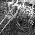 “Sawhorse” in the garden
Memories of childhood and adolescence stay with a person for life: of the native log house with a Russian stove; of sun-warmed dusty paths in the garden and vegetable patch, of the...
