TIME RELAY FOR HALF AN HOUR

TIME RELAY IN HALF AN HOURJust 30 minutes will it take to build a simple and reliable time switch that at a given point (in the range of 1-11 h) will switch on or off any home appliance power up to 0.5 kW. The device is made on the basis of a conventional mechanical clock, for example, “amber”, “Sevani”, “Ray”, in a plastic case of which a simple device consisting of two neon lamps T-0,3, a pair of resistors VS-0,25 or MLT-0,5, the micro-switch MP-1, socket for standard plug and fuse.

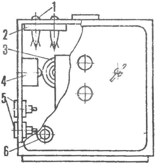
The principle of operation of the time relay is simple. The coiled flat spring tzonka the alarm of Moscow extends beyond the movement, until you hit a Cup call. This fact makes it easy to turn alarm clock to timer — is enough to remove the bell Cup, and in its place install a switch. Now the clock spring, releasing the stored energy, the outer revolution rests not in a Cup to call, and click on the “button” switch, which, in turn, complete the circuit power supply external device — tape recorder, radio, lamp, electromarket (safe hot plate with the temperature of the working surface of no more than 95 ).
 
Neon lamp V1 (Fig. 1) indicates the device is connected to the network, and V2 indicates a voltage at the sockets x2. Resistors R1, R2 limit the current through V1 and V2. S1 — micro-switch actuated by a spring clock. Fuse F1 protects the unit from possible short circuit.
Signal arrow mounted on the right time, wind the watch and alarm clock, plug X1 include the network and connect the load. At a predetermined point in alarm hours, and the spring call will close the contact S1: indicator lights lamp V2, and the voltage goes to the load.
 
Adding the switch S2 (Fig. 2) you can install two modes: “turn load on” and “off load”. In the first case, it works similar to the previous one. When switch S2 the circuit to the load is closed, at the set time, switch S1 opens it.
 
Fig. 1. Electrical diagram of a first embodiment of the time switch.
 
Fig. 1. Electrical diagram of a first embodiment of the time switch.
 
Fig. 2. Electrical diagram of a second embodiment of the time switch.
 
Fig. 2. Electrical diagram of a second embodiment of the time switch.
 
Mount elements time relay in the case it is easy. Need only a knife, drill, needle files, glue, pencil erasers and file. The quality of the work depend on the “commodity” of the device and its reliability.
 
The microswitch and the “nonki” fastened by means of pencil erasers (Fig. 3). One of them sharpened knife cut a groove the size of the microswitch, so after installing it looked only “a little button”, and in the workpiece with an awl pierce holes for the wires.
Then secure the microswitch with the second eraser, gluing him to the side surface of the first side of the recess. For this fit, glue BF, “Supercement” or similar. After it dries, trim the glued block in width and height. The last set depending on the distance of the external coil unwound spring to the wall of the watchcase. Measure it, after compressing the spring in 1 — 3 turns, thus providing the necessary force with which to further it will push the “button”, erasers and glue a microswitch to the case.
 
R and p. 3. The block switch.
 
R and S. 3. The block switch.
 
R and p. 4. The location of the elements of the time switch in the housing of the alarm clock
 
R and S. 4. The location of the elements time relay in case of alarm:
 
1 neon lamp, 2 — holder, 3 — spring, 4 — switch, 5 — socket, 6 — fuse.

 
The third will go to the eraser holder manufacturer of neon lamps. Make it two holes by 1-2 mm smaller than the diameter of the glass cylinders “neonat” and by installing the holder in the upper part of the body, drill two more holes. To not damage the” plastic case, this work must be performed carefully, first outlining the future of the awl holes; then drill the intermediate hole Ø 1 — 2.5 mm. To the desired size they are adjusted by a drill of appropriate diameter, or a knife. A round needle file to remove the bumps. The surface of the eraser with the grease holes with glue, insert them in neon lights and fasten on the case.
 
Last install socket and fuse holder by drilling for them in the intended parts of the body necessary holes (Fig. 4). Under the fuse holder in the lid or in the housing of a needle file to make a groove for the power cord.
 
Switch S2 (see Fig. 2) can be placed on top of the housing to the right of the regular buttons mute alarm sound or on the bottom on the right side of the housing opposite the nests. In that case, however increase the risk of damage to the pendulum clock.
 
Now proceed with the installation. In:e connection, run the insulated wire, carefully checking the reliability of the rations and connections.
A. KABANOV

Recommend to read

  • HANGERS FOR SHOES…HANGERS FOR SHOES…
    Wooden rod nailed to it curved from a metal strip sheds — a convenient option unusual coat hanger to facilitate drying wet shoes: it is enough to hang it in a warm place, deciding only...
  • FUNNY TOPTANCIFUNNY TOPTANCI
    Kids like stilts, but not in any age they are available to them: kids are difficult to be controlled by them. And unsafe: some no, but height, but still sticks... But these are unusual...