WELDING OF… NOTHING

WELDING OF... NOTHINGDesign welding transformer I have, so experience in this are. I want to offer the readers of my last — as it seems the most successful — the development of a welding machine is not entirely conventional design.

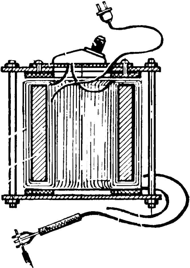
The peculiarity of this device is that the core of the transformer represents the stator end-of-life induction motor. The choice of the core is determined by the cross sectional area of the stator — it should be at least 20 cm2. If this condition is satisfied, fit a stator from any of the asynchronous engine. Well, the cross-sectional area is determined as shown in the figure.


I will mention that the most rational cross section of the stator-core lies between the values of 20 cm2 and 50 cm2. In principle, suitable cores with an area less than 20 cm2, however, it will have to reduce wire size in the primary and secondary windings of the transformer, which will greatly reduce the power of the unit and narrow its possibilities. But the use of cores with cross-sectional area more than 50 cm2 irrational: the transformer at its base it turns out unnecessarily bulky and heavy, and this, too, is not a virtue portable welding machine.


Remove the stator from the frame of the engine is not too difficult. This can be done using a hacksaw and a small hammer. To start engine with removable front and rear covers together with the anchor. Then the cutter need to make a couple of cuts thus, as shown in the figure. Drank the deep, but be careful not to damage the stator. Just know this: the deeper propyl — even easier and without damage be able to remove the stator from the housing.

Now a good hit with a sledgehammer next to one and other cuts. Usually several blows to the hull collapsed and the stator windings were freed from it.

 
The coil burned-out engines to use, as a rule, is impossible, so it will have to remove with pliers and scissors for cutting metal.
 
Releasing the stator from the winding, you get a billet core welding transformer. It is only necessary to remove the jumpers from winding grooves under will get you ready the core. For this purpose, a conventional chisel and hammer. It is most convenient to remove the jumpers from first one end and then the other. Warned that must work in protective glasses, in an isolated room. Make sure also that there were breakable objects. Cutting teeth, try as close as possible to the base, and preferably flatter.
 
Fig. 1. The main parameters of the induction motor stator, necessary to convert it into a transformer core
Fig. 1. The main parameters of the induction motor stator, necessary to convert it into a transformer core:
a — height of the cross section of the core, b is the width of the cross section of the core, S is the cross — sectional area of the core.
 
Fig. 2. Preparatory operations for extracting the stator from the motor housing.
 
Fig. 3. The stator winding of cotton tape
Fig. 3. The stator winding of cotton tape:
1 — the stator (transformer core), 2 — duct tape, 3 — hook with electrical tape.
 
After removal of the teeth, the cotton core is wrapped with insulation tape — this will protect the first windings from sing breakdown on the body. The isolation is conveniently wound with a special hook, cut from plywood, as shown in the figure. By the way, the same Shuttle will take you to winding wire on the core.
 
The primary winding of the transformer is best obtained from a wire in cotton insulation. The cross section can be chosen in accordance with table 1. For the secondary winding to be “lived” in the rubber insulation — the kind used in power cables.
Table 1
 
Table 1.
In table 1 the following notation is used:
 
S1 square transverse cross-section of the primary winding;
 
S area of cross section of the core is equal to the product of the height of the core in its thickness;
 
W1 is the number of turns of the primary winding of the transformer;
 
W2 is the number of turns of the secondary winding of the transformer;
 
S2 square of the cross – section of the secondary winding of the transformer;
 
W3 — additional windings, wound with the same wire as the primary winding W, is used to control the welding current.

 
The additional winding W may have from two to five additional branches, but in principle, it is possible to do without it, leaving only a single winding W. At the same time, however, a slightly lower efficiency of the welding machine.
 
Fig. 4. Schematic diagram of the welding transformer.
 
Fig. 5. Welding machine DC.
 
Fig. 6. Universal device for welding with alternating current and starting the car with direct current.
 
Fig. 7. Design welding transformer
Fig. 7. Design welding transformer:
1, 2 — power cables, 3 — mount transformer, 4 — nut 5 — screw pin, 6 — a transformer core, 7 — coil, 8 – screw fixing top panel, 9 — upper panel 10 — contactor (power outlet), 11 — jumper (mains plug with a jumper), 12 — power cord 13 — a plug welding machine.
 
As can be seen from the diagram of the transformer, welding current is controlled by contactor ЅА1. On panel fixed several standard network sockets — the number depends on the number of conclusions of an additional winding. The contactor is the power plug, in which the legs of the connector are connected by a solid wire with a diameter of 1/4 the diameter of the wire of the primary winding. This gives the possibility to use the contactor as a fuse which operates at undesirable loads.
 
I would like to warn those who will not be able to get a wire for the primary winding of a suitable cross-section that is not a reason to not take on the establishment of the welding machine. It is possible to pick up some wires so that their total cross section would not be less than recommended for W. In principle, you can even use uninsulated wire, wound with her own cotton tape. Similarly, you can pick up wire for the secondary winding. By the way, this was exactly what I had to do when building your welding machine. Thus to isolate the wire it took ten skeins of narrow cotton tape, which can be purchased at hardware stores or electrical stores.
 
I would like to warn you that after winding the primary winding should not be immediately filled, and the secondary — first you have to check it out. This primary winding is connected via a fuse which is cut the copper wire with a diameter of 0,1…0,15 mm. If the coil is not buzzing and not heated, this means that the work you have carried out efficiently and you can start winding the secondary winding. If the fuse burns out is a clear sign of closed loop. From this it follows that the primary winding will have to reel in again, paying particular attention to the quality of the wire insulation. But if the coil is not heated, but bugged quite a loud buzz, then it means that you made a mistake when counting the turns and you were less than recommended in table 1. In this case, it is necessary to podmochat another few turns and repeat the test.
 
Order welding machine was universal, the secondary winding of the need to make a branch from the third part of the coils and connected through the transformer to the powerful diode of the rectifier — so “of puskach” for the car which is especially useful during the cold season, which significantly extend the life of your car’s battery.
Note that the use of powerful rectifier diodes with a direct current of not less than 200 And will allow you to weld parts arc DC — this gives better ignition and a smoother seam. If the magnitude of the forward current of the diodes lies in the range from 50 to 200 And, in this case, a device for welding with alternating current to run the car rectified current.
 
Note that a correctly assembled transformer requires no configuration and immediately after the Assembly is ready for operation. Of course, when performing welding work must comply with all the safety precautions recommended when working with electrical appliances. In particular, never touch the live parts; all the switching modes of the welding machine must be performed only when disconnected from the network. Welding work should be carried out in a special mask and overalls, not from splashing of hot metal and light radiation on the exposed areas of the body.
 
If you are in the process, meet any hardship, willing to share their experiences, answer any questions on the design of my welding machine and its work.
 
My address: 654000, Novokuznetsk, Kemerovo region, Kirov str., 10, kV 3.
 
Vasiliy DRUZHININ, engineer

Recommend to read

  • THE NEWCOMER BECOMES “SNIPER”THE NEWCOMER BECOMES “SNIPER”
    What is a shame to damage the car at the entrance to a private garage! Unfortunately, this happens with young drivers is not so rare, especially if the garage is to put it mildly, does...
  • FOLDER-IMPROMPTUFOLDER-IMPROMPTU
    My uncle came up with an unusual "folder", but somehow does not dare to write to you; he considers it a trifle. However, someone also might come in handy: it is easy to manufacture and...