Key stage actuating relay K1 needs to include emergency power, such as additional battery (Executive relay contacts are not shown in the diagram). In this embodiment, when the audio node is not needed, the elements DD1.4, DD2.1, DD2.2, C3, R5, R6 are removed.
The principle of operation of the device
DC voltage range 4,5 – 15 V (Ewha woman), withdrawn from the network adapter to the input device and the smoothed oxide capacitor C1 (C50-24), passes through the diode VDV1 (KD521, KD522, Д220 with any letter index), limiting resistor R1 and to an input of the logical element FF1.1. This element can be included as an inverter. Then the normal state of its output low level voltage (logical “0”), Normal conditions suggests the presence of AC voltage 220V To the lighting network.
On the elements DD1.2, DD1.3 implements the unit of memory with two stable States is a logical trigger.
With the disappearance of the reference voltage, the Ewha woman at terminal 5 DD1.2 set high level. The same level will be present at the output 10 of the element DD1.3 and will remain here until you remove the voltage from across the electronic unit with the reset button (not shown in the diagram), or remove the connector from the battery (see below).
Through a current limiting resistor R4, the voltage of high level is input to pulse generator implemented on the logic elements DD1.4, DD2.1, DD2.2. Chain C2R2 allows you to set the trigger condition, eliminating false positives.
The pulse generator (audio frequency) is a logic “1” coming to the entrance of DD1.4 (output
12 IC). Pulse frequency is determined by the values of the elements C3 and R5. If specified in the diagram the values of the oscillator frequency is approximately 800 Hz.
VD1, the transistor works as a current amplifier. Due to this, the quality of the sound emitter BZ1 you can apply a wide range of devices: from piezoelectric capsule type ZP-Z high DC resistance (impedance) to a dynamic telephone capsules, resistance above 50 Ohms.
Electric circuit device sensor with audible alarm power outage
Thus, while the input of the first element DD1.1 comes a voltage (controlled device in good condition) to pin 4 of the element DD2.2 is a logical “O” and silence in an audio capsule BZ1.
As soon as the measured voltage is lost, the generator starts. The trigger on the elements DD1.2, DD1.3 saves its state and the resumption of the controlled power supply Ubx, so the generator, even after the voltage recovers, runs continuously.
Again to bring the scheme to a state of readiness (to reset trigger) you need to briefly disconnect battery GB1, then remove and again apply power Ubx. The connection of the battery is performed after applying a voltage to contacts Ubx. Battery and the measured voltage is connected to the device via connector РП10-11 or similar.
To adjust the tone of the generator can change the capacitance of the capacitor CP. With decreasing capacity the pulse rate increases. Common wire the power circuits and controlled by the schema should be connected.
If necessary, the automatic inclusion of the reserve voltage source or an additional alarm to the point “A” connects the node to the transistor with the actuating relay K1. VD2 diode prevents reverse shots of the current through the relay coil in the moments on-off switch K1, thereby protecting the transistor and eliminating the contact bounce of the relay.
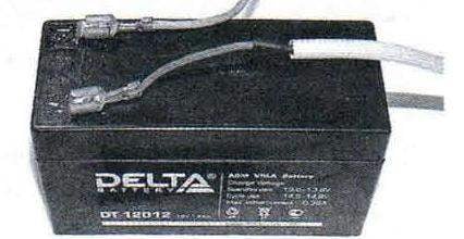
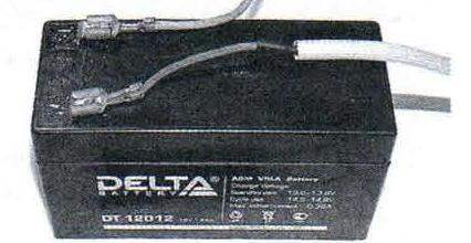
The scheme is implemented on two chips of CMOS К561ЛЕ5, no setup required, works stably 24 hours and easy to repeat. As a standalone battery has a battery DT12-012 capacity of 1.2 Ah or similar, for a voltage of 12 V. the GB1 is possible to use batteries.
Recommended battery DT12-012
The current consumed by the circuit elements in the standby mode (at high voltage level at the input of the chip DD1.1), is only 8 mA. The practices established that a charged battery is enough for 3 – 4 months continuous operation of the device in the standby mode. Therefore, in this scheme there is no need to connect the GB1 through the diode in the forward direction (for constant recharging from AC adapter) – you can ruin the battery.
Installation components and replacement parts
AC adapter (power supply Ubx) can be any brand.
The elements of the device mounted on the circuit Board. The transistor VT1 type КТ312, KT315 with any alphabetic index. All fixed resistors type MLT-0,25. Electrolytic capacitors K50-6, K50-12 or similar. The Sz condenser – type КМ6 or similar. Relay K1 (if necessary use) thin, the trigger voltage of 7 – 9V, for example RES-15 (performance RS4.591.003). For reference: nominal current Executive relay RES-15 circuit 220 V total 150 mA.
A. KASHKAROV, G. s a n t-P etersburg
Recommend to read AT PEST — A FIRE EXTINGUISHER There are many different tools, devices, equipment, value of which is primarily determined practical purpose, and their appearance and technical aesthetics are of secondary importance. I... “HELLO” — “MOSCOW” I homebrew with years of experience, have built and snowmobiles, and ATVs. But my biggest passion is boats. Despite today's gloomy everyday worries, I still find time to do what you...