AND FOR THE JOINER AND CARPENTER

TO THE JOINER AND THE CARPENTERPlease tell about your Hobbies. Like to create: to create with their hands the things that enhance the comfort and beauty home. I especially like working with wood — carpentry, carpentry. The desire to have in your use of “helper”, accelerating the work and improving its quality, was the main motive for the creation of the present combined machine for obtaining joinery blanks, and you can tell the woodworking mini-complex.

My practical, although some experience in industrial machines for woodworking and cutting, proved to be very useful in the design and manufacture of this mini-complex. Now it can be used to produce the different processing: sawing (both in longitudinal and transverse direction of fibres); planing; grinding and polishing, turning and drilling (you don’t know — it is difficult to list all) products of wood, and some operations even metal.
 
Mini-complex consists of two, in General, independent of the machines (except that the first is used for the second base or support). The first is a circular saw with electroparka. Second — lathe-drilling machine.
 
Today we will talk about the first look at its device details But from the outset, he designed, so to speak, by aggregate the scheme (knives of the jointer and circular saw have the same drive and fixed on one work shaft — rotor). This decision allowed me to make the design more simple and feasible, which undoubtedly affected the rational distribution of the main components and assemblies. In this machine there are sites such as industrial manufacture and commissioned professionals and, of course, made with his own hands. There are even unusual details, for example, the support portion of the machine — frame, nothing like the “feet” from an old sewing machine. And she successfully entered in the General design is practically without alterations, or rather the width of the table of the planer to adjust to her proper size. The main part of the base (side bars, cross member, remote of the substrate) was made of channel No. 5. Both designs: frame and frame — welded.
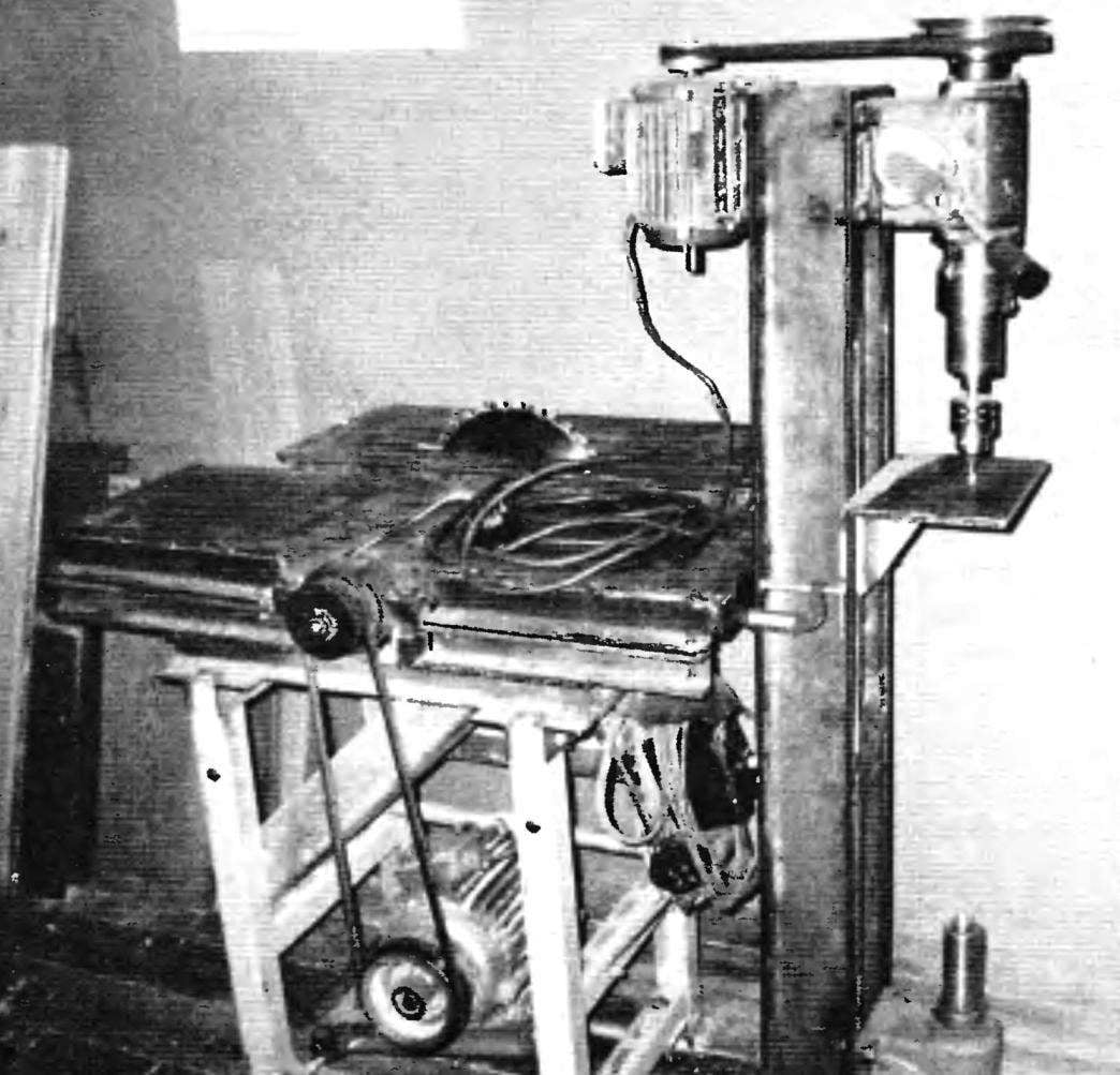
Installed on the machine three-knife rotor with bilateral (double-edged) knives of the jointer, saw blades, carbide tipped, various kinds of devices allow to obtain products made of sawn timber of high quality. In the planing mode (planing) width of the processed surface is 260 mm and cutting depth up to 2 mm.
 
Drive jointer and circular saw
 
Drive jointer and a circular saw
 
Tables (suction and discharge) of the jointer and the control panel (in the foreground)
 
Tables (suction and discharge) of the jointer and the control panel (in the foreground)
 
Woodworking machine—surface planer and
 
Woodworking machine—surface planer and “circular saw”:
 
1—frame (from the foot of the sewing machine, pressed steel channel 50x50x50, 4 pieces); 2—hinged sub area; 3—additional front frame for fastening the lifting table “buzz-saws” (area 50×50, 2); 4—pan (dural sheet s1,5); 5—longitudinal drawer side (rolling channel No. 5,2 PCs); 6—podstolny remote substrate (rolling channel No. 5, 4x); 7—circular saw (Ø300×32); 8—control panel; 9—the sub-frame lifting table “buzz-saws” (area No. 5); 10—lifting mechanism of the table “buzz-saws” (Jack); 11—transverse drawer side (rolling channel No. 5 2); 12—jointer; 13—slave pulley; 14—V belt (2); 15—drive pulley V-belt transmission; 16—electric motor (N=3 kW, n=1500 Rev/min U=380 V); 17—cross connection (steel profile, 4 PCs.); 18—the outlet table of the jointer; 19—the receiving table of the planer; 20—lifting table “buzz-saws”; 21 —guiding device facing (pipe Ø17); 22—the bearing housing of the working shaft (2 PCs.)

 
The rotor (or shaft work) is the most important, complex and responsible part of the machine. Besides, it is common for a jointer and circular saw. I made (or rather ordered to Turner and then the milling machine) according to the drawings published in the article “Small but universal” V. Autoja from the Belarusian city of Grodno in the journal “modelist-Konstruktor” No. 11 for the year 2003. But since this detail is very responsible, and publication was long enough, here is the drawing of the rotor again, especially since it made your changes: for example, lengthened blades, and thus the rotor seats (axle) for other bearings etc.
 
In the same issue of the journal “assembled” and the lifting mechanism of the table “the saws” — height adjustment it on the machine, replacing a circular saw on a suitable mill (or the same saw for single or multiple passes), you can fetch slots, “quarters”, and folds of various sizes.
The saw blade has a diameter of 300 mm and allows for a single pass to provide maximum cutting height (or groove depth) up to 80 mm. the cutting edges of the boards at different angles helps the fixture mounted on the edge of your desktop circular saw. This sliding mechanism (call it a saddle) is very convenient when processing the end edges of the Board.
 
The reliability of this machine has been checked in the process of creating another machine — lathe. Working on his bed, I spent three hours straight slotted longitudinal rails oblong holes (slots) on the upper shelves of its channels using cutoff wheels installed in place of the saw blade, and then produced their grinding.
 
Table of the jointer
 
Table jointer:
 
1, the longitudinal strapping element (area 45×45,2); 2—rear element binding (area 45×45); 3 — front element binding (area 45×45); 4—top (steel sheet s5)

 
Frame under engine platform
 
Frame sub-sites:
 
1, the longitudinal strapping element (pressed steel channel No. 5, 2 PCs); 2 — cross-element binding (pressed steel channel No. 5,2 PCs); 3—lug suspension frame (steel sheet s5. 2); 4 — cross connection frame; 5 — lug cross-connection (steel sheet s5. 2); 6—axis of the suspension frame (steel, circle 20); 7—pin

 
The rotor of the jointer and circular saw
 
The rotor of the jointer and circular saw:
 
1 —screw M8 with spring washer; 2—pressure washer Ø35×25 (steel, sheet s4); 3—driven – pulley; 4—housing cover bearing (2 PCs); 5—bearing 18037 (2); 6—bearing housing (2); 7—rotor (45 steel); 8— Circlip; 9—disc blades; 10 pressure washer; 11—nut M20; 12—clamping strip knife (3 pieces); 13—knife jointer, 3). 14—strut (M6 screw, 12 PCs.)

 
Lifting table of a circular saw with the mechanism of the facing of the blanks
 
Lift table saws with the mechanism of the facing of the blanks
 
In the middle of the frame (half the length) a work shaft, bearing assemblies which is secured to it by bolts M20x1,5, length 70 mm. shaft Drive is on the left side. When viewed from the side of the working space, the left part is the knife part of a planing head. On the right side of the shaft neck diameter of 32 mm. depending on the operation it can be set: circular saw, milling, sanding, grinding or cutting wheel. Important! Nut of fastening of the tool on the shaft is right-hand threaded. Working surface of the machine is formed of three steel plates (tables). Two plates located on either side of the planer rotor (shaft). First — receiving table, is closer to the carpenter, the second table outlet. Both table have the same dimensions. A special mechanism for height adjustment relative to the cutting tool at the outlet there were and this operation is carried out as necessary with steel shims.
 
Surface tables are made from steel sheet with a thickness of 5 mm in the form of inverted trays (or troughs) is installed in the frame of the corners of 45×45 and welded thereto.
Table saws, on the contrary, in the process, can be easily exhibited at the height of the saw blade with the integrated lifting mechanism. On the right side of the table “buzz-saws” on the longitudinal guide mechanism is placed with the scale adjusting the angle, by which it is possible to produce stippling of the ends of boards, not only direct, but also at any angle in between. The basis of this mechanism taken as a suitable tool for hand saws.
 
Notice that the described fixture can be easily removed: removed or lowered. The longitudinal guide rail is made of steel pipe with a diameter of 17 mm, its fixing is done using brackets, Ushkov on the edges of the table circular saw.
 
On the same side of the table by means of the clamping bar bolts M10 to the table is mounted a guide strip made of rolled steel angle 50×50 mm. distance between the saw blade and strap is determined by the width of the cut workpiece. And she strap helps to maintain a predetermined width along the entire length of the workpiece without marking the latter.
 
Hoist table
 
The lifting mechanism of the table “buzz-saws” and the mount table of the guide:
 
1 —frame, 2—resistant cross member frame (50×50 area); 3 —Jack (screw М20х2); 4—resistant cross member of the lift table (area 45×45); 5—stopper lifting table (special screw M12x1,5,2); 6—circular saw; 7—guide bar; 8—drawer side (area 40×40, 4x); 9—stand lifting table (area 40×40, 2); 10—strut (40×40 area, 2); 11—countertop; 12—additional front frame; 13—clamping bar (steel, 2); 14—poluchili-lock nut M10 (2 sets.); 15—special screw M10 2 PCs.)

 
Mechanism for end-milling of blanks
 
A mechanism for the parallel machining of workpieces (parts of POS. 3,4,6 used from attachments for hand saws):
 
1—Foundation (Board s15); 2—focus (Board s18); 3—front (steel); 4—the plate scale (steel); 5—fastening of the plate to the base (bolt M8 2); 6—the stopper (special nut M8 knurled); 7—fastening of the bushing to the base (nut M8 2 PCs); 8—lifting table “buzz-saws”; 9—bracket mounting rail to the table (sheet s5, 2 PCs.); 10—guide rod (pipe Ø17); 11 —backing plate (steel, sheet s5); 12—bushing (steel, 2); 13—fastening of the guide rod (screw M12 2 PCs.)

 
The drive of a rotor — work (instrumental) shaft — carried double-strand V-belt transmission (although in practice I use only one strap) from the three-phase (380 V) motor power 3 kW with a speed of 1500 rpm. The engine is located at the bottom inside the frame and pivotally mounted to the suspended cantilever subframe, which allowed to solve the problem of belt tension without additional video. To ensure the quality of processing the material, the rotational speed of the working shaft has been increased due to the accelerating belt transmission. The drive pulley diameter of the motor is larger than the diameter of the pulley working shaft in half, therefore, the knife rotor and a circular saw rotating with an angular speed of about 2250 rpm. The motor power supply is via four-core cable, wiring done with all the requirements of safety standards, the frame is grounded. In case of short circuit or overcurrent starting machine is capable of almost instantly the power is switched off in automatic mode. After work, the machine should be shut down, cleaned of chips and dust.
 
The machine has been operating for six years. Spend routine maintenance: syringes bearing, check condition of mounting the knives of the jointer, the condition of the teeth of the saw blade, inspect V-belts for the drive and power cables of the machine.
 
Not superfluous to recall that the machine refers to the mechanisms of increased danger. The rotating parts are not used and cutting tools, you must close the fixed covers. The work on the machine requires the utmost concentration, compliance with safety regulations. Do not rush, do not force to speed up the process, work hard at your pleasure. The workplace of the joiner should be well lit, the space around the machine is free enough, the flooring is not slippery.
 
S. yakishev in a, p. Shapkino, Krasnoyarsk Krai

Recommend to read

  • Cordoba for every tasteCordoba for every taste
    The Soviet school of construction of model aircraft air combat has long since gained worldwide recognition. Although it is possible to speak about the attempts to find new opportunities...
  • THE SMOOTH SURFACE OF CONCRETE…THE SMOOTH SURFACE OF CONCRETE…
    For casting concrete columns (e.g. for a fence) gardeners often use wooden formwork. Ugly get posts that came from this form, rough, rough... Make the form with plastic wrap, and a few...