Today we can safely say: if you want to get a good result in competitions, use an engine with a “colored” piston-cylinder pair! This is confirmed by the “colored” filling of the motorcycle mounts of the models that have won the highest rank championships.
Knowing the undeniable advantages of such engines, many take on the task of independently producing new pairs. And they immediately encounter many difficulties, unknown factors and quantities. For them – the story of the USSR Master of Sports Yu. Mussalitin about applying chrome coating to parts made of various metals.
Chrome plating, one of the coatings most needed by engine engineers, is one of the most labor-intensive electroplating processes. It requires special care and cleanliness both when preparing the electrolyte and the substances themselves that make up its composition. The water used is distilled or (only as a last resort!) thoroughly boiled.
START WITH THE BATH
Start your lessons in model electroplating by making a bathtub. First of all, select a 10 liter saucepan and a three liter glass jar. It is better not to use smaller containers – this can complicate the adjustment of process parameters, and even with the given values, the volume of the bath is only enough for chrome plating 6-8 cylinder liners.
Having glued the body from 1-1.5 mm plywood, assemble the bathtub according to the given figure and cover everything with a plywood ring. Work on the bathtub ends with turning out the lid of the pan and installing heating elements and a contact thermometer on it.
Now – electrical equipment. To power the bath, you can use any DC source with an 80,000 uF X 25 V electrolytic capacitor connected at the output. The power wires must have a cross-section of at least 2.5 mm 2 . A sectional rheostat can serve as a current regulator that replaces a voltage regulator. It is connected in series with the galvanic bath and consists of parallel sections switched on by single-pole switches. Each subsequent one has twice the resistance of the previous one. The number of such sections is 7-8.
1 – internal casing (10 liter pan), 2 – casing (plywood 1-1.5 mm thick), 3 – thermal insulation (fiberglass), 4 – thermal insulating layer (asbestos chips, sand, glass wool), 5 – tubular electric heater heating element, 6 – contact thermometer, 7 – three-liter glass container (jar), 8 – lid (delta wood).
On the front panel of the power supply, install two 15 A sockets, one with normal polarity, the other with reverse polarity. This will allow you to quickly carry out anodic treatment of the part and switch to chrome plating by simply rearranging the fork. Sockets with three outputs, so as not to make a mistake in polarity (of course, only two sockets are connected).
To maintain a constant temperature of the electrolyte, the bath is equipped with a contact thermometer. It cannot directly control the operation of heating elements due to high currents, so you will need to assemble a simple device, the diagram of which is shown in the figures. Thermoregulator parts: transistors MP13—MP16, MP39—MP42 (VT1); 213—217 (VT2) with any letter designations; resistors MLT-0.25, diode – D226, D202-D205; relay – TKE 52 PODG or OKN passport RF4.530.810.
Adjusting the thermostat: if the relay does not operate when shorting points 1-2, connect the emitter and collector VT1. Turning on the relay indicates a malfunction or low gain of VT1. Otherwise, transistor VT2 is faulty or has insufficient gain.
Having assembled and adjusted the structure of the bath, you can begin preparing the electrolyte. To do this you need:
– pour a little more than half of the prepared distilled water, heated to 50°, into the jar,
– add chromic anhydride and stir,
– add water to the calculated volume,
– pour in sulfuric acid,
— work the electrolyte for 3-4 hours at the rate of 6-8 A g/l.
The last operation is necessary to accumulate a small amount of Cr3 ions (2-4 g/l), the presence of which has a beneficial effect on the process of chromium deposition.
ELECTROLYTE COMPOSITIONS
Chromic anhydride – 250 g/l or 150 g/l
Sulfuric acid – 2.5 g/l or 1.5 g/l
DON’T FORGET ABOUT CHROME MODES!
The chromium plating process is highly dependent on the electrolyte temperature and current density. Both factors affect the appearance and properties of the coating, as well as the current efficiency of chromium. It must be remembered that as the temperature increases, the current efficiency decreases; with increasing current density, the current output increases; at lower temperatures and constant current density, gray coatings are obtained, and at elevated temperatures, milky coatings are obtained. The optimal chromium plating mode has been found in practice: current density 50-60 A/dm 2 at an electrolyte temperature of 52° – 55° ±1°.
To be sure that the electrolyte is working, you can coat several parts in the prepared bath, similar in shape and size to the working samples. Having selected the mode and found out the current output by simply measuring the dimensions before and after chrome plating, you can begin to coat the sleeves.
According to the proposed method, chromium is applied to steel, bronze and brass parts. Their preparation consists of washing the surfaces to be chrome-plated with gasoline and then soap (using a toothbrush) in hot water, loading them into a mandrel and placing them in a bath. After immersion in the electrolyte, you need to wait 3-5 seconds and then turn on the operating current. The delay is necessary for the part to warm up. At the same time, the surface of parts made of brass and copper is activated, since these metals are easily etched in the electrolyte. However, you should not wait more than 5 seconds – these metals contain zinc, the presence of which in the electrolyte is unacceptable.
CHROMING ALUMINUM ALLOYS
Special attention should be paid to the processes of applying chromium to aluminum alloys. The implementation of such coatings is always associated with a number of difficulties. First of all, this is the need to first apply an intermediate layer.
DETERMINATION OF THE CONTENT OF CHROMIC ANHYDRIDE CrO 3 DEPENDING ON THE SPECIFIC GRAVITY OF THE SOLUTION
| Specific gravity at 15° | CrO 3 content, in moles | CrO 3 content in g/l |
|---|---|---|
| 1.07 | 1.00 | 100 |
| 1.08 | 1.14 | 114 |
| 1.09 | 1.29 | 129 |
| 1.10 | 1.43 | 143 |
| 1.11 | 1.57 | 157 |
| 1.12 | 1.71 | 171 |
| 1.13 | 1.85 | 185 |
| 1.14 | 2.00 | 200 |
| 1.15 | 2.15 | 215 |
| 1.16 | 2.29 | 225 |
| 1.17 | 2.43 | 243 |
| 1.18 | 2.57 | 250 |
| 1.19 | 2.72 | 272 |
| 1.20 | 2.88 | 288 |
| 1.21 | 3.01 | 301 |
| 1.22 | 3.16 | 316 |
| 1.23 | 3.30 | 330 |
| 1.24 | 3.45 | 345 |
| 1.25 | 3.60 | 360 |
| 1.26 | 3.75 | 375 |
| 1.27 | 3.90 | 390 |
| 1.28 | 4.06 | 406 |
| 1.29 | 4.22 | 420 |
| 1.30 | 4.38 | 438 |
| 1.31 | 4.53 | 453 |
| 1.32 | 4.68 | 468 |
Aluminum alloys containing a large amount of silicon (up to 30%, alloys of the AK12, AL25, AL26, SAS-1 grades) can be chrome-plated as follows:
– washing the part in gasoline, – washing in hot water with washing powder or soap,
– processing the part in a solution of nitric and hydrofluoric acids (ratio 5:1) for 15-20 s,
– rinsing in cold water,
— installation of the part on a mandrel and chrome plating (loading into a bath under current!).
It’s another matter if it is necessary to coat the AK4-1 alloy with chromium. It can only be chromed using an intermediate layer. These methods include: zincate treatment; along the nickel sublayer; through nickel salt; through anodic treatment of the part in a solution of phosphoric acid.
In all cases, the parts are prepared as follows:
— grinding (and lapping);
— cleaning (removal of fat deposits after grinding in gasoline or trichlorethylene, then in an alkaline solution),
– washing in running cold and warm (50-60°) water,
— etching (to remove particles remaining on the surface after grinding and lapping, as well as to improve the preparation of the surface of the part for the application of chromium).
For etching, a caustic soda solution (50 g/l) is used, the processing time is 10-30 s at a solution temperature of 70-80°.
For etching aluminum alloys containing silicon and manganese, it is better to use the following solution, in parts by weight:
nitric acid (density 1.4)—3, hydrofluoric acid (50%)—1.
The processing time for parts is 30–60 s at a solution temperature of 25–28°. After etching, if it is a cylinder liner, it must be immediately washed in running water and immersed in a solution of nitric acid (50%) for 2-3 seconds, followed by rinsing with water.
INTERMEDIATE COATINGS
Galvanizing
Aluminum products at room temperature are immersed for 2 minutes in a solution (caustic soda 400 g/l, zinc sulfate 120 g/l, Rochelle salt 5-10 g/l. Or: caustic soda 500 g/l, zinc oxide 120-140 g/l) with constant stirring. The coating is quite uniform and has a gray (sometimes blue) color.
If the zinc coating is uneven, the part is immersed in a 50% nitric acid solution for 1-5 seconds and after washing, galvanizing is repeated. For magnesium-containing aluminum alloys, double galvanizing is mandatory. Having applied the second layer of zinc, the part is washed, charged into a mandrel and, under current (without applying voltage, the zinc has time to partially dissolve in the electrolyte, contaminating it) installed in the bath. First, the mandrel with the part is immersed in a glass of water heated to a temperature of 60°. The chrome plating process is normal.
Nickel plating (chemical)
If zinc does not adhere to aluminum (most often this happens on the AK4-1 alloy), you can try to apply chromium through nickel. The operating procedure is as follows:
– surface grinding,
– degreasing,
– etching for 5-10 s in a solution of nitric and hydrofluoric acids mixed in a ratio of 3:1,
– nickel plating.
The last operation is in a solution of the following composition: nickel sulfate 30 g/l, sodium hypophosphite 10-12 g/l, sodium acetate 10-12 g/l, glycol – 30 g/l. It is first prepared without hypophosphite, which is introduced before nickel plating (with hypophosphite, the solution is not stored for a long time). The temperature of the solution during nickel plating is 96-98°. You can use the solution without glycol, then the temperature should be reduced to 90°. In 30 minutes, a layer of nickel with a thickness of 0.1 to 0.05 mm is deposited on the part. Dishes for work – only glass or porcelain, since nickel is deposited on all metals of the eighth group of the periodic table. Brass, bronze and other copper alloys lend themselves well to nickel plating.
After nickel deposition, heat treatment is carried out to improve adhesion to the base metal (200-250°, holding time 1-1.5 hours). Then the part is mounted on a mandrel for chrome plating and lowered for 15-40 s into a solution of 15% sulfuric acid, where it is treated with reverse current at the rate of 0.5-1.5 A/dm 2 . Nickel is activated, the oxide film is removed, and the coating becomes gray. Only chemically pure acid should be used (in the worst case, battery acid). Otherwise, nickel will turn black, and chrome will never fit on such a surface.
After this, the mandrel with the part is loaded into the chrome plating bath. First, the current is given twice as much, then within 10-12 minutes it is reduced to working current.
Defects of electroless nickel plating:
– nickel plating does not occur: the part has not warmed up, you should wait a while,
– spots on the surface (typical of AK4-1): poor heat treatment of the part, it needs to be heat treated at 200-250° for 1.5-2 hours.
Removal of nickel from aluminum alloys can be done in a solution of nitric acid.
Sometimes during the nickel plating process, self-discharge occurs—precipitation of powdered nickel. In this case, the solution is poured out, and the dishes are treated with a solution of nitric acid to remove nickel from its surface, which will interfere with deposition on the part.
I would like to note that nickel-phosphorus itself has very interesting properties that are not inherent in chrome coatings. This is the uniformity of the layer on the surface of the parts (after deposition, finishing is not required); high hardness after heat treatment (400° mode for an hour gives a coating hardness of HV 850-950 and more); low coefficient of friction compared to chromium; very slight expansion; high tensile strength.
Nickel-phosphorus without further application of chromium can be used not only as an intermediate coating on liners, but also as a working coating, reducing friction and wear, for spools and piston pins. After two years of active operation of the engine with parts of such a finish, there was no obvious wear on them, characteristic of hardened steel surfaces.
Applying chromium through nickel salt
The whole process boils down to this:
— etching in caustic soda solution (50 g/l, t=80°, 20 s),
– washing in running water,
– application of the 1st intermediate layer (nickel chloride, 1 min),
— etching off the intermediate layer in a nitric acid solution (50% acid solution, 1 min),
– application of the 2nd intermediate layer (nickel chloride, 1 min),
– washing with water,
— etching (nitric acid 50%, 15 s),
– washing in running water,
— loading into a chrome plating bath under current.
Chromium application via anodic treatment
Instead of intermediate layers, anodic treatment can be performed in a solution of 300-350 g/l phosphoric acid at a temperature of 26-30 °, a terminal voltage of 5-10 V and a current density of 1.3 A/dm 2 . The bath should be cooled. For alloys containing copper and silicon, a solution of 150-200 g/l of phosphoric acid is used. Mode – 35°, processing time 5-15 minutes.
After anodic treatment, a short-term cathodic treatment should be carried out in an alkaline bath, which partially removes the oxide layer. Research has shown that during the anodic treatment of aluminum alloys in phosphoric acid, a rough surface is formed on the parts, which promotes strong adhesion of the subsequently applied coating.
DEVICES, MANDARDS
Chrome plating of the sleeve
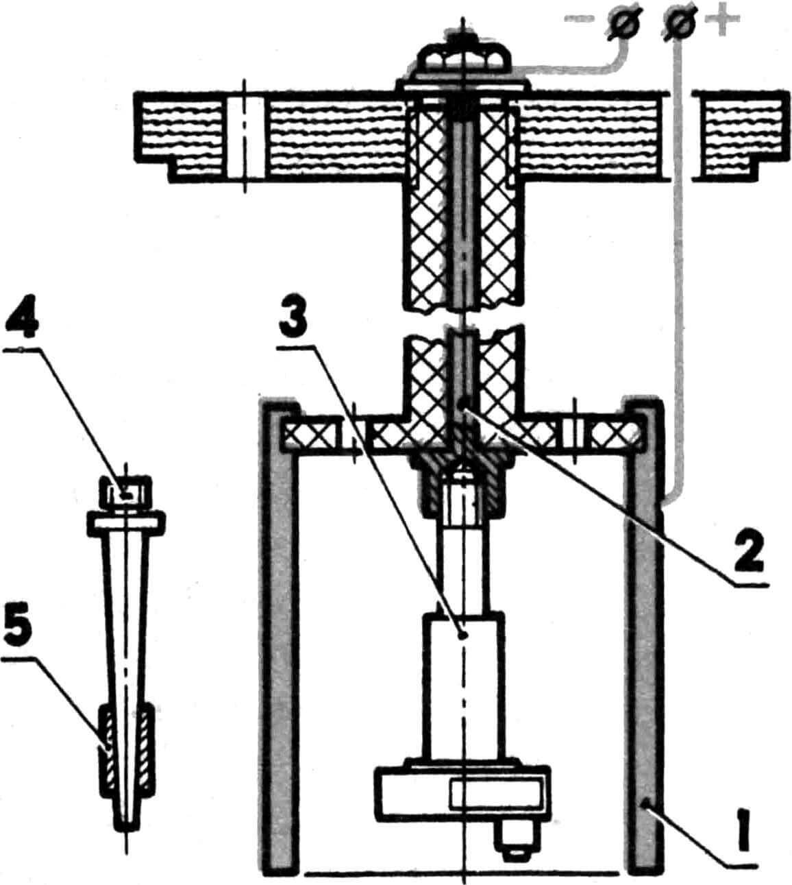
To perform work with the cylinder liner, a mandrel is made. Its structure is clear from the given figure; we will dwell only on individual details.
Anode – steel pin; Lead and antimony (7-8%) are fused at one end over a length of 50-60 mm. Lead is machined along the outer diameter up to 6 mm (for sleeves with a working diameter of 15 mm). On the other side of the stud, a thread is cut to secure the wire.
1 – cover (vinyl plastic), 2 – upper part of the mandrel (fluoroplastic), 3 – lower part of the mandrel (fluoroplastic), 4 – anode (steel), 5 – cathode, 6 – through window for the passage of electrolyte, 7 – coated sleeve, 8 – insulator attachment.
The cathode is a ring with an internal diameter 0.5 mm larger than the internal size of the sleeve. A piece of insulated wire is stamped into it. It is better not to use copper and brass conductors – the electrolyte dissolves them and the contact may be broken. Before installing the mandrel in the bath, it is useful to check the reliability of the contacts with a tester.
Chrome plating of steel parts (crankshaft, crank pin, piston pin, bearing races)
Chrome plating of steel parts is carried out using the following technology: – removal of grease stains using gasoline,
– wash in hot water and soap,
– treatment of the part with reverse current for 2-3 minutes,
– switching to chrome plating mode with a current 2-2.5 times greater than the calculated one, and a gradual decrease in current over 10-15 minutes.
The calculated current is determined by multiplying the area of the chrome-plated surface by the process current. For steel, the last value is 50 A/ dm2 . When chrome plating, for example, a seat for the main bearing on the crankshaft of a KMD-2.5 engine, the calculated current will be equal to 0.03 dm2X50 A/dm 2 = 1.5 A.
1 – anode, 2 – cathode, 3 – crankshaft, 4 – conical mandrel, 5 – piston pin.
A new mandrel will be needed to chrome the crank pin. As when processing the crankshaft, all open surface areas are covered with AGO glue. The anode is machined from steel, followed by filling with lead and boring a hole for the finger. The use of a steel part is explained by the need to ensure reliable contact – threaded connections in lead are unreliable. Current calculations are similar. The work is carried out in the shaft mandrel using a special attachment.
There is practically no difference between chrome plating of bearings. The only thing is that to protect the inside of the part, it is filled with grease or other grease, which is washed out with gasoline after application of the coating.
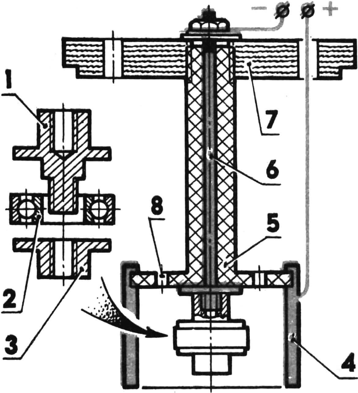
1 – bearing mandrel housing, 2 – ball bearing, 3 – figured nut, 4 – anode (lead), 5 – central part of the mandrel for chrome plating, 6 – cathode (steel), 7 – cover, 8 – through window for the passage of electrolyte.
The concentration of chromic anhydride in the electrolyte is monitored using a hydrometer. The concentration of sulfuric acid can only be determined, unfortunately, indirectly, by the quality of the coating.
During the chrome plating process, the electrolyte evaporates. In these cases, add water to the required level. This is done without installing parts – it is possible to change the temperature of the electrolyte.
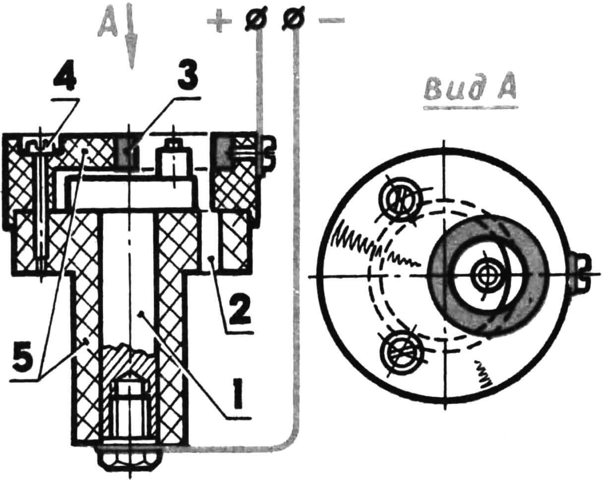
1 – crankshaft (aka cathode), 2 – through window for passage of electrolyte, 3 – anode, 4 – cover fastening screw, 5 – mandrel parts (fluoroplastic).
After chrome plating, all products are subjected to heat treatment for 2-3 hours to remove hydrogen, at a temperature of 150-170 °. All work is carried out under a suction device, wearing rubber gloves and goggles.
CHROME DEFECTS AND THEIR CAUSES
1. Chrome does not settle on the product:
– poor contact at the anode or cathode,
– There is little cross -section of the conductors,
– on the surface of the anode, a thick film of oxides formed (removed in a solution of hydrochloric acid),
– Mala current density,
– the temperature of the electrolyte is high,
– Little distance between electrodes,
– Excess sulfuric acid.
2. The coating exfoliates:
– poorly degreasing the surface,
– The current supply was broken,
– fluctuations in temperature or current density.
3. On the surface of chromium – craters, holes:
– hydrogen is delayed on the surface of the part – change the suspension so that the gas is freely removed,
– on the surface of the base metal there is a graphite,
—The surface of the main metal is oxidized, pryst.
4. On the protruding parts, a thickened coating:
– increased current density.
5. The coating is hard, exfoliates:
– Mala is a current density, the temperature of the electrolyte is increased,
– In the process of chromation, the temperature of the electrolyte changed,
– In the process of grinding, the product overheated.
6. Chrome does not settle around the openings of the details:
– a large release of hydrogen – close holes with Ebonite traffic jams,
– Excess sulfuric acid.
7. Brown spots on the coating: – lack of sulfuric acid, – an excess of trivalent chromium (more than 10 g/l) – withstand the bathtub under the current without parts, increasing the surface of the anodes and reducing cathodes.
8. Soft “milk” coating: – the temperature of the electrolyte is high, – the current density is small.
9. The coating is matte, uneven, is difficult to rub:
– The lack of chromium anhydride is great current density – a lack of sulfuric acid – an excess of trivalent chromium.
10. The coating is spotted and matte: – In the process of chrome, current supply was interrupted,
– The product before loading was cold.
11. In some places, the coating is brilliant, in others matte:
– The current density is great,
– The temperature of the electrolyte is low, – the current density on the protruding and in -depth parts of the part.
Yu. Musalitin, USSR master of sports
Recommend to read
 NOT A PILL, AND LIGHT
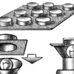
Now, many medicinal tablets are Packed in colorful plastic cells, covered with foil or paper. In improvised signal light devices are very convenient to use such cells as the cap-filter... A STEP WITHOUT A SKELETON!
What a pity that in his childhood the wise advice of adults fly in one ear and immediately out at another. Remember the many comments of parents and teachers like "straighten up!" or "sit...
