In the household there is occasionally a need for longitudinal sawing of long boards into beams or battens, trimming chipboard (particle board) to size, or performing similar operations with other comparable building or furniture materials. Anyone who has done such work with a hand saw knows how tedious and laborious it is, especially when several cuts are needed, when working with hardwood, or when cutting old lacquered chipboard whose binder has hardened and the finish has glazed.
Buying a factory circular saw for these purposes is not only costly but also impractical given the sporadic nature of the work—storing it requires space that is already scarce in an urban apartment.
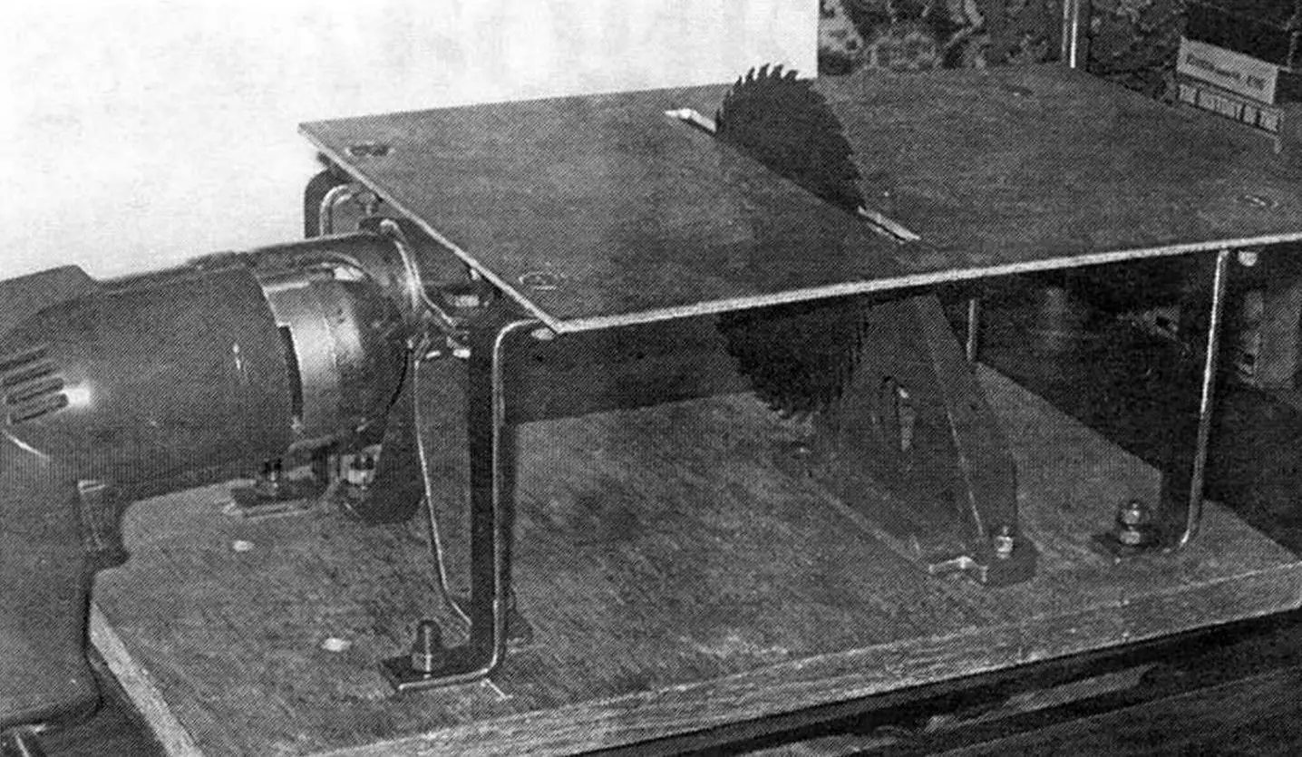
In that situation I built a simple, compact, and collapsible “circular saw” driven by an electric drill. After each use I quickly and easily disassemble the unit into separate parts, which I store in a tool cabinet, and the drill continues to be used for its intended purpose.
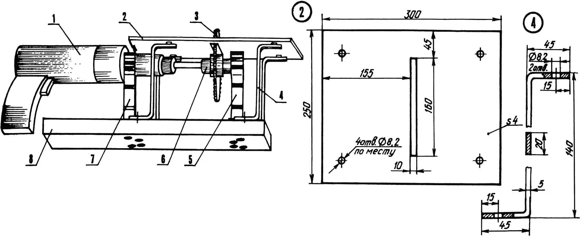
1 — drive (electric drill); 2 — work table (duralumin, 5 mm sheet); 3 — circular saw blade; 4 — stand (St3 steel, 20×5 strip, 4 pcs.); 5 — support holder for mandrel shaft; 6 — mandrel; 7 — drill holder; 8 — base plate (furniture chipboard, 30 mm)
The entire assembly (without the drill) consists of a base, a work table, four stands between them, and two holders: for the drive (electric drill) and for the free end of the saw blade shaft.
The base is made of furniture (faced) particle board 300×250 mm and 30 mm thick.
For the table (work surface) a rigid duralumin plate 4 mm thick was used, with a transverse slot 160×10 mm cut roughly in the middle (for the maximum intended saw blade diameter—160 mm in my case). The table can also be made from steel sheet of similar thickness, but then the unit becomes heavier. Chipboard is not advisable for this—to achieve sufficient stiffness its thickness would have to be large, which would reduce the maximum thickness of workpieces that can be cut.
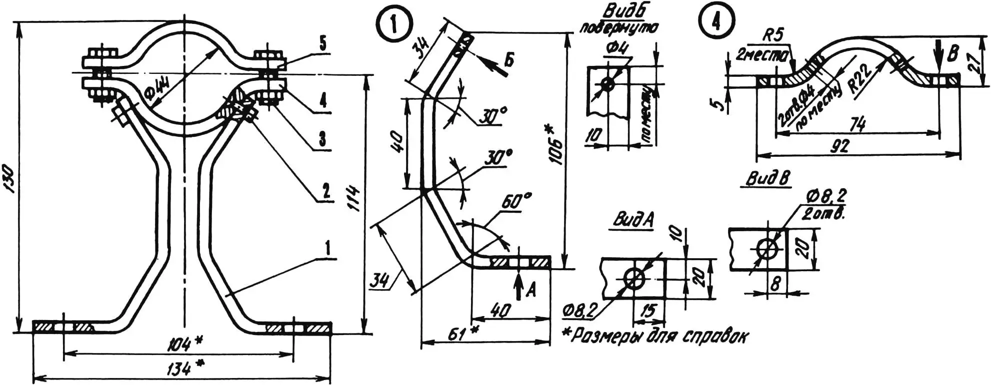
1 — leg (St3, 20×5 strip, 2 pcs.); 2 — rivet (steel, Ø4); 3 — M8 bolt with nut (2 pcs.); 4 — lower bracket (St3, 20×5 strip); 5 — upper bracket (St3, 20×5 strip)
The drill holder is homemade. It is made from steel strips 20×5 mm in cross section. The holder has two legs and a clamp formed by a pair of brackets with lugs. The bracket radii match the cylindrical part of the drill gear housing. The lower bracket is riveted to the top ends of the legs with 4 mm steel rivets. Holes in the bracket are countersunk and the rivet heads are flush. Holes for M8 bolts are drilled in the lugs of both brackets; the brackets are tightened with these bolts to clamp and secure the drill. In the upper bracket the holes were made in advance; in the lower one they were drilled in place (using the upper bracket as a guide). The same holes are drilled in the stand feet. The shaft holder was a ready-made part, though it could be made the same way as the drill holder.
The four stands of the circular saw are made from the same material as the holder—20×5 mm steel strip. Their horizontal feet at the ends are bent in opposite directions like the letter Z. Holes for M8 bolts are drilled in the feet. When making the stands, one difficulty is determining their height. It must be such that the edges of the cheeks clamping the saw blade and the drill chuck do not hit the bottom of the work table, while the table should not sit too high above them, which would again reduce the maximum workpiece thickness.
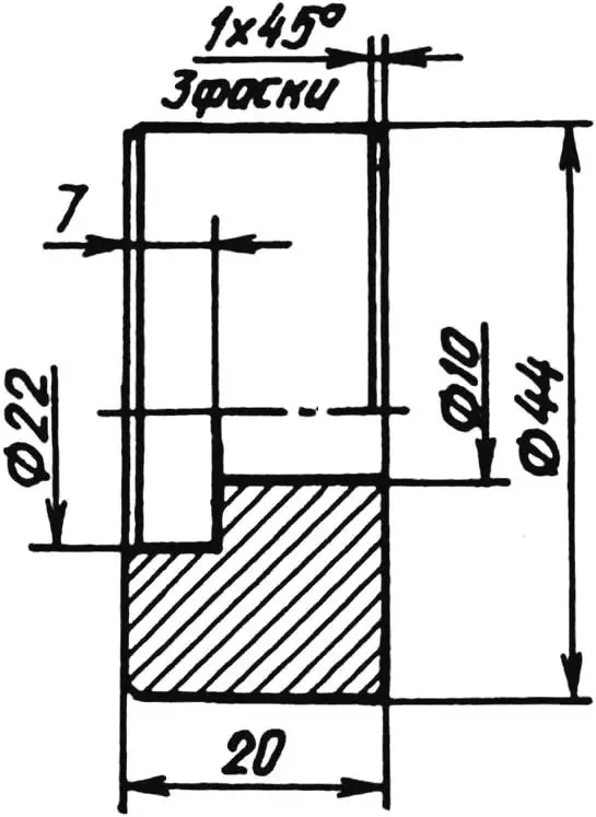
A relatively complex part of the circular saw is the mandrel, which consists of the drive shaft for the saw blade and the parts that secure it. The shaft is stepped. The diameter of its left portion, as well as its length, are determined by the maximum size that can be gripped by the drill chuck. The next step has a slightly larger diameter, and on the third step (25 mm diameter) flats are made for an open-end wrench.
The next step is a flange. Its diameter (42 mm in my design) is chosen so that the flange together with a special M10 clamping nut provides a reliable grip (friction hold) of the saw blade.
Then comes the portion on which the saw blade is mounted, with a minimum bore of 12.6 mm. Blades with larger bores are mounted on this portion using adapter rings.
After that comes a step with M10 thread. A special clamping nut is screwed onto it; the diameter of its larger step is the same as the flange. On the smaller step of the nut (25 mm outside diameter) and the locknut, flats for a 22 mm wrench are filed, as on the third step of the shaft. The clamping nut is secured against loosening by a special locknut, although loosening is only possible after the saw is off, when the mandrel spins freely due to the inertia of the large-diameter blade.
At the end of the shaft a 7 mm journal is made for bearing 80027 (7×22×7 mm, d×D×B, where d is bore, D is outside diameter, B is ring width). Bearings of the 80 series have two protective washers, since there is a lot of wood dust here during operation. The bearing is housed in a body that is in turn clamped between the clamp brackets of the holder. Besides the bearing seat, a through hole is drilled in the body so the shaft can be driven out when disassembling. The assembly can also use suitable double-sealed bearings of the 180 series. If neither series is available, the design must provide protection for standard bearings with seals or gaskets.
All parts and subassemblies of the circular saw are fastened with M8 countersunk-head bolts (except the clamp brackets—they use standard bolts). The heads are sunk flush into the parts (under the base plate and on top of the work table) and do not interfere with placing the saw on any suitable table or working on it.
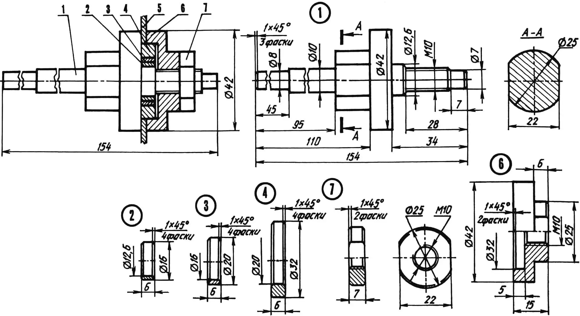
1 — shaft (steel 45, Ø44 bar); 2,3,4 — adapter rings (St3); 5 — saw blade; 6 — M10 clamping nut (St3, Ø44 bar); 7 — special M10 locknut (St3, Ø25 bar)
I assembled the circular saw in the following order. First I clamped the housing with the bearing inserted in it in the holder clamp. Then I fixed the saw blade on the shaft. To do this I clamped the shaft in a vise by the “key” flats and slid on the required bore ring(s) and the blade (teeth in the direction of shaft rotation). I screwed the clamping nut and locknut onto the thread. Next I secured the drill in the holder and the corresponding end of the mandrel shaft in its chuck. I inserted the other end of the shaft into the bearing bore.
After that I drew the centerline on the base and placed the assembled drill, mandrel, and holders along it. I also marked on the base the holes for attaching the holder legs and the stands. I drilled the holes, countersunk them from below, inserted M8 countersunk-head bolts, and fastened the holder legs and stands with nuts from above. Having the nuts on top makes assembly, adjustment, and disassembly easier.
Then I placed the work table on the stands so that the saw blade in its slot had equal clearance from the slot edges. Using the holes in the upper feet of the stands, I marked the centers of the matching holes on the table from below, drilled them, and countersunk them from the top for M8 countersunk heads. When fastening the table to the stands I also adjusted its position relative to the blade using washers, placing them between the stand feet and the work surface and on the bolt shanks.
To use the circular saw I clamp its base to the workbench with clamps, with the drill on the left and the end of its handle resting on the bench in a tilted position.
I check runout of the saw blade with short bursts of the drill and correct it by restoring alignment of the drive components using tin half-rings in the clamps and washers under the holder feet.
The circular saw design allows mounting a saw blade up to 160 mm in diameter on its mandrel and cutting workpieces up to 50 mm thick.
If needed, to maintain a precise and constant width of the cut-off part, a guide made from a piece of metal angle can be mounted on the work surface, fastened with bolts through slots in it.
When using the drill-powered circular saw, simple safety rules must be followed. Feed workpieces smoothly, without skewing, and avoid stopping or jamming the blade. Before stopping the machine, first separate the workpiece from the blade, then switch off the drill.
«Modelist-Konstruktor» No. 10’2003, D. DVOENOSOV
Recommend to read
 UNUSUAL GIFT
It's a letter to the editor. In it two leaves of sketches on the reverse side of which a short description and a few photos of the model. No return address, no signature of the author.... Homemade sprayer
I made it for treating plants in the fight against garden and vegetable pests. I assembled it from available materials, mainly an electric motor from a sewing machine and a gear oil pump...
