
This lock is suitable for a garage door-gate or even a garage, whether from inside or outside. It is sturdy because it is massive and has no shackle into which a burglar can insert a crowbar (against which, as is known, there is no defense). In principle it is similar to the design already described («Modelist-Konstruktor» No. 8’98), but is made differently.
The lock consists of a body, a pin, a latch, two pins, a screw, and a key.
The body is screwed on by its M14 threaded hole onto the bolt end that sticks out from the gate (leaf) at the required spot; the bolt is welded on the other side to an angle bracket so it cannot turn.
To lock, turn the latch until its slot aligns with the pin hole, then pass the pin through the eye of the leaf to be locked and insert it into the body hole until it stops. Then turn the latch again counterclockwise by 90° and, through the 3 mm diameter holes in the latch disk, use the key-screwdriver to move the pins out of the “open” position by tightening (or loosening) them in turn until they stop.
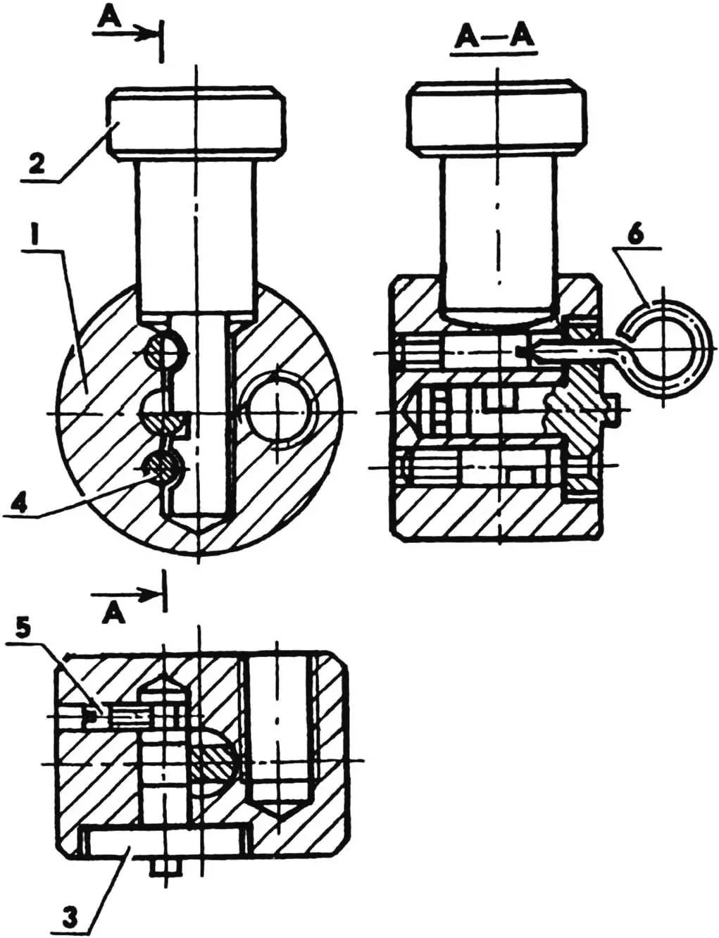
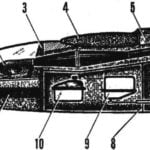
1 — body; 2 — pin; 3 — latch; 4 — pin (2 pcs.); 5 — screw; 6 — key-screwdriver
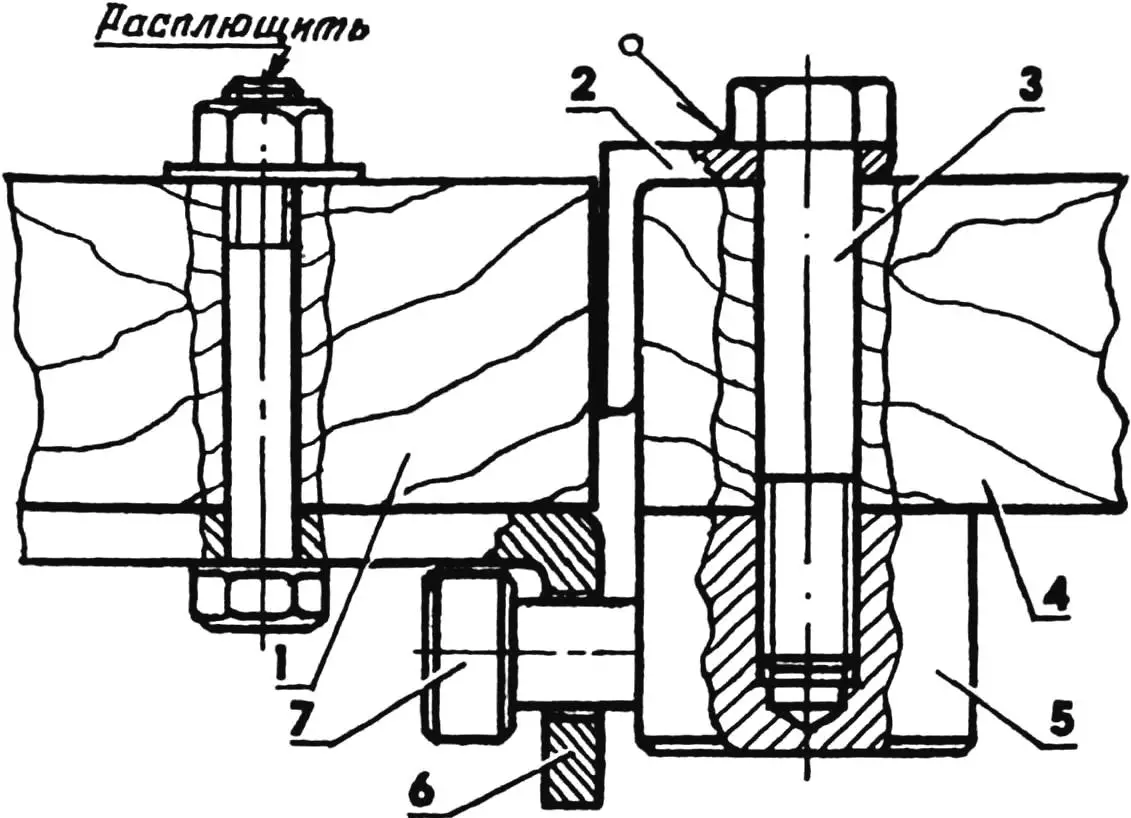
1, 4 — gate leaves; 2 — bolt reinforcement angle; 3 — M14 lock mounting bolt; 5 — lock; 6 — eye; 7 — lock pin
To unlock, turn the latch counterclockwise until it stops and, with the key-screwdriver through the holes in the latch, turn the pins in turn by the number of half-turns that matches the lock code, from the extreme position they were moved to when locking into the “open” position. Then remove the key, turn the latch clockwise 90°, and pull the pin out of the body. The latch acts as a blocking device that prevents the pin from contacting the locking elements and pins when unlocking, so the lock code cannot be felt out.
LOCK MANUFACTURING
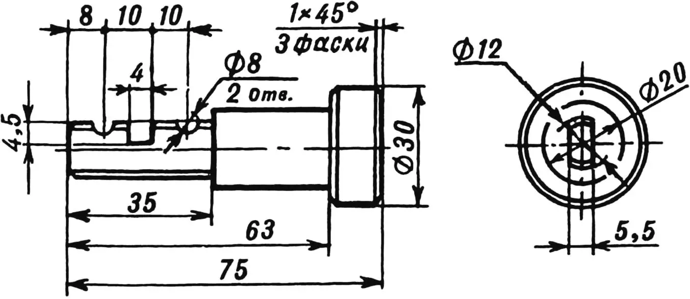
1. Turn the pin (steel 40Kh) on a lathe according to the drawing (Fig. 4).
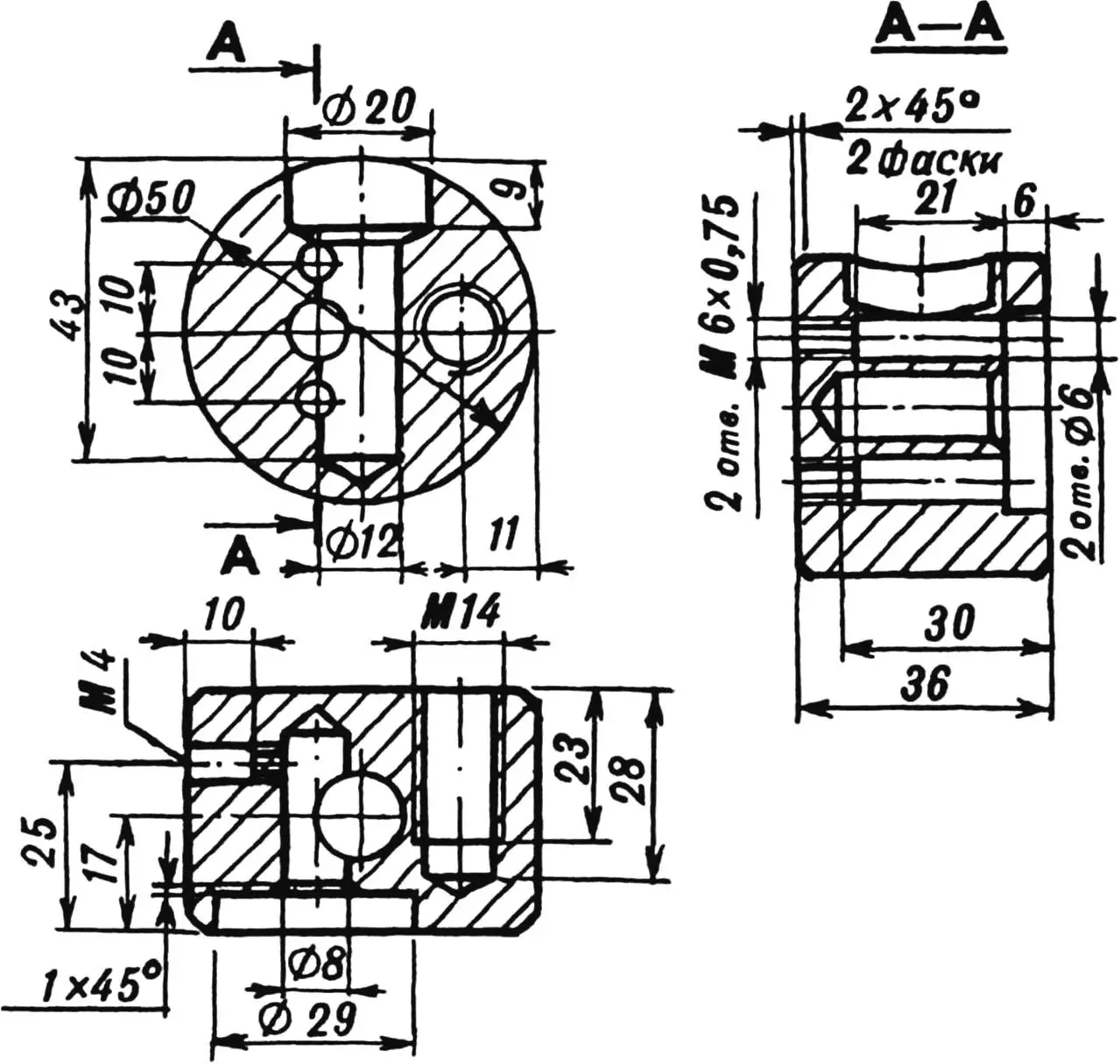
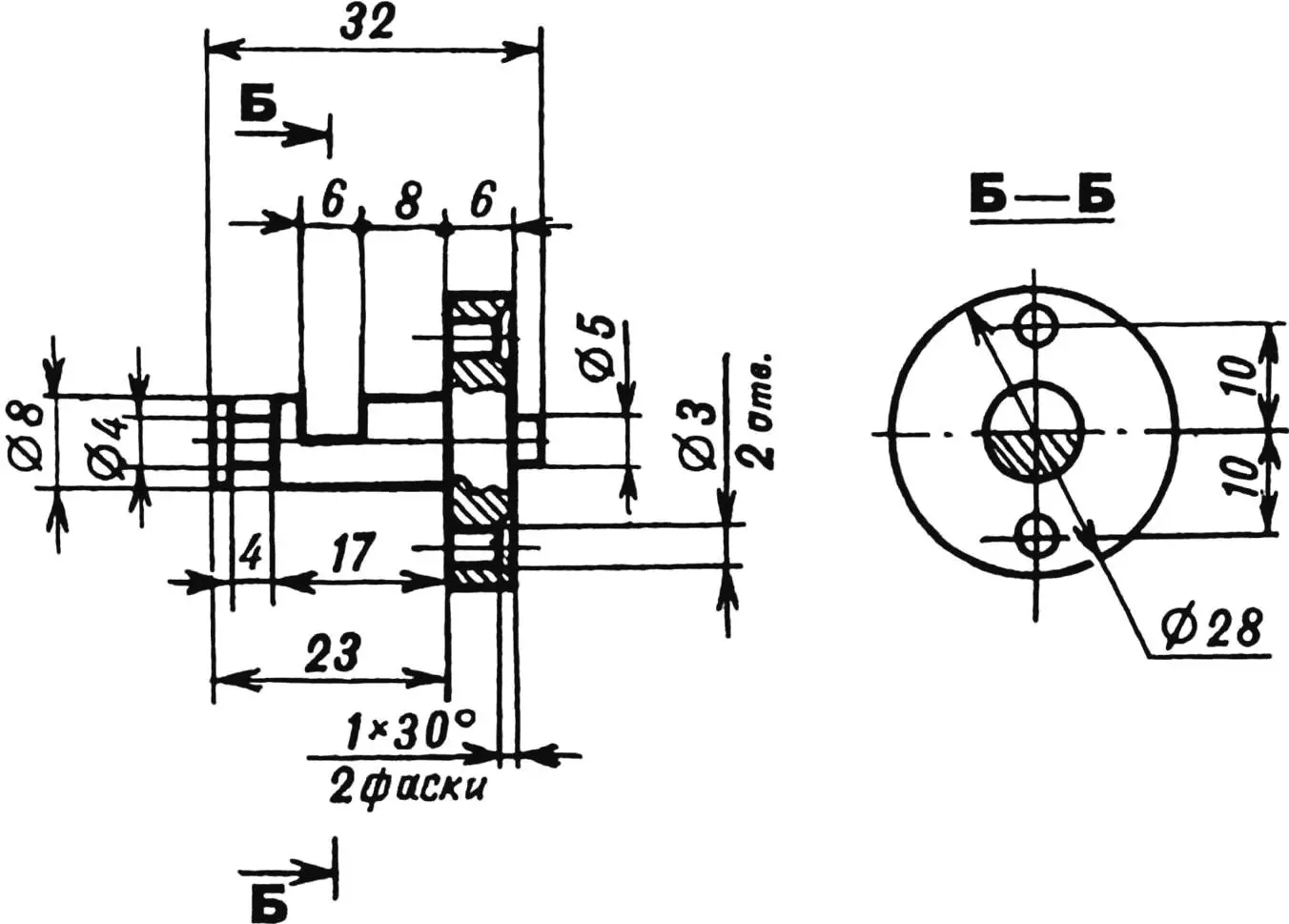
2. Machine the front and cylindrical surfaces of the blank (steel 20) for the body (Fig. 3).
3. Using the end of a boring tool with the spindle stationary and longitudinal and cross feeds, scribe layout lines on the cylindrical (generatrix) and front (diameter) machined surfaces.
4. Chamfer.
5. Cut the body blank to size.
6. Mark and center-punch the centers of the following holes: 12 mm diameter — on the generatrix from step 3 and 4 mm diameter — on the cylindrical surface; 8 mm and 6 mm (2 holes) — on the front; M14 — on the rear surfaces.
7. Drill radial holes: 12 mm diameter — to a depth of 43 mm, then bore to 20 mm diameter to 9 mm depth, and 4 mm diameter — to 10 mm depth; also end holes: 6 mm diameter (2 holes) 10 mm deep and for M14 thread.
8. Insert a steel mandrel into the 12 mm diameter hole (to prevent drill drift), chuck the body with offset, and drill an 8 mm diameter end hole to 30 mm depth.
9. Bore the body end to 29 mm diameter and 6 mm depth.
10. Drill a through hole for M4 thread in line with the 4 mm diameter radial hole.
11. Tap M4 and M14 threads.
12. Insert the pin into the body until it stops, deepen one 6 mm diameter hole in the body to 21 mm (from the bore plane).
13. Fix the pin in the body with a 6 mm diameter mandrel in the hole drilled in step 12, and deepen the second 6 mm diameter hole to 21 mm.
14. Drill through holes for M6×0.75 thread in line with the 6 mm diameter holes in the body.
15. Tap M6×0.75 thread in both holes (fine thread is used to increase lock secrecy).
16. Machine the 12 mm diameter section of the pin to 5.5 mm width; the flat surfaces are perpendicular to the axes of the recesses made in steps 12–13.
17. Bring the recess radii to 4 mm (to resist code picking); cut the rectangular slot to the dimensions shown in Fig. 4.
18. Make the latch (steel 40Kh) according to the drawing (Fig. 6).
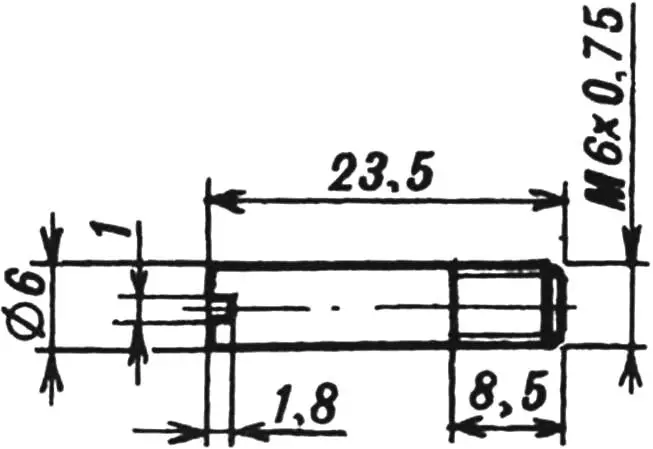
19. Turn two pin blanks (steel 40Kh) according to the drawing (Fig. 7).
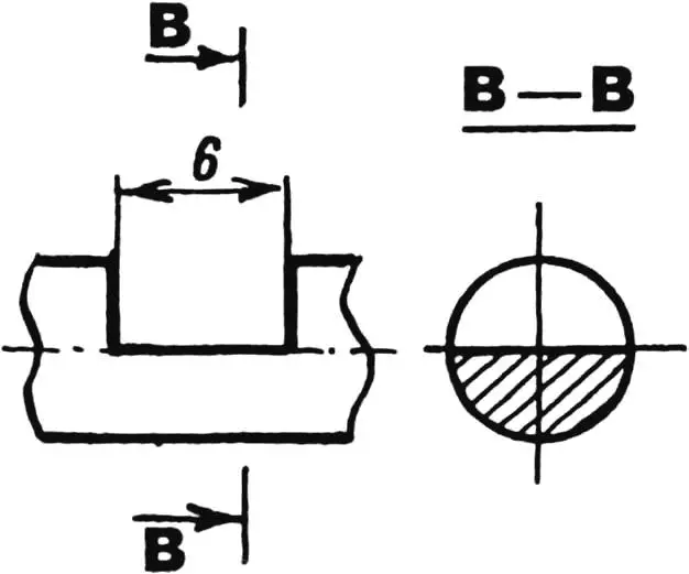
20. Cut one slot each on the cylindrical sections of the pins in arbitrary positions (Fig. 8) so that the slot angle to the flat bottom is the same on both pins. This is needed so both pins are “open” in one angular position of the key.
LOCK ASSEMBLY
21. Screw the pins into the body so their slots are in the middle of the pin hole and form a passage for it.
22. Insert the latch into the body until it stops and turn its slot toward the pin hole. Insert the pin into the body with its recesses toward the pins until it stops to check that the pin enters in the “open” position of the lock mechanism. Adjust if needed.
23. Check that the latch grips the pin by turning the latch 90° counterclockwise. The pin should then be firmly held in the body.
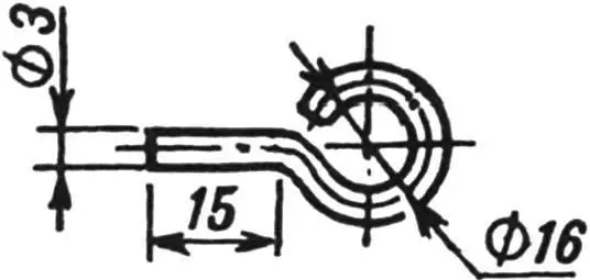
24. Make the key blank (3 mm diameter steel wire) according to the drawing (Fig. 5).
25. Grind the key end to a screwdriver shape with the blade at such an angle that the ring of the key in the slot lies in the plane of the 6 mm diameter holes (see section A–A in Fig. 1). When fitting the key, hold the pins in the “open” position by inserting the pin (with the latch removed) into the body the other way, i.e. with the recesses away from the pins.
LOCK TEST
26. Insert the latch. Tighten the screw (Fig. 1) until it stops, then loosen it half a turn.
27. Determine the lock code by checking the “open” position (see step 22), removing the pin, turning the latch 90°, and tightening the pins with the key in turn until they stop, counting half-turns of the key including partial ones. The number of half-turns for each pin is its code. You can do the same by tightening the pins until they stop, using the fully loosened position as the reference.
28. Verify the code by loosening (or tightening) the pins by the number of half-turns that match the code; on the last half-turn align the key ring to plane A–A (this can be done by feel using the “pin” in the center of the latch disk, which is for orienting the key ring when unlocking in the dark) before removing the key; turn the latch 90° with the slot toward the hole and insert the pin into the body. If the pin goes in fully (check by fixing it as in step 23), the code is correct — write it in a hidden place and memorize it.
29. Disassemble the lock, heat-treat the pin, pins, and latch to HRC 46…50; apply zinc coating to the body, pin, and latch; grease the parts with consistent grease; assemble the lock for use.
«Modelist-Konstruktor» No. 8’2001, I. YANKIN, Baikonur, Kazakhstan
Recommend to read
 MODEL CLASS F3B
The fuselage is laminated entirely of fiberglass, applying resin To Tina-153. The bow compartment to the first frame filled with foam PS-1, which cut the slots for placing the battery...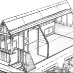 FLOOR UNDER THE ROOF
When we get a country house, sometimes don't assume that after a dozen years, the once spacious and comfortable, it will be close: first, grow up children, then grandchildren, and the...
