This device can quickly and accurately measure, for example, the temperature of a human body, water, and air. An electronic thermometer is needed by agricultural workers to determine the temperature of grain, potatoes, and soil, and by medical workers.
The thermometer consists of five main units: a temperature-to-frequency converter, a rectangular pulse generator, a pulse counter with a decoder, a power supply, and an indicator (Fig. 1).
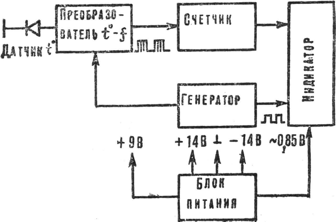
The first unit converts the direct voltage drop across the sensor diode into frequency. The signal at the converter output is filled with rectangular pulses coming from the generator and then fed to the counter, which converts the input frequency into a code for controlling seven-segment indicators. During pulse counting, the indicators do not light up — they are locked by a signal coming from the generator unit, which also generates a reset pulse at the end of the indication cycle.
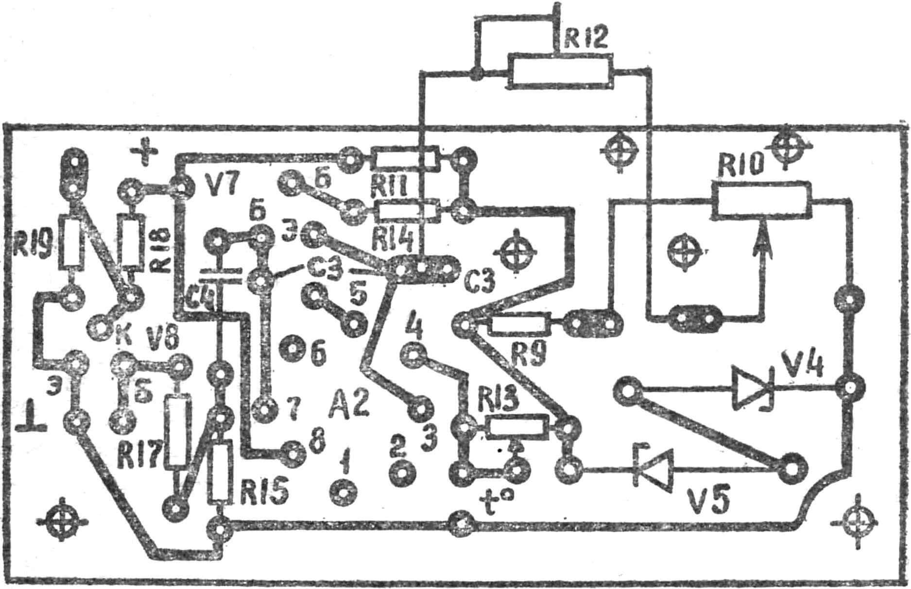
The circuit diagram of the thermometer is shown in Fig. 2. The temperature sensor is diode V7 of type D9, the voltage drop across which is used for the integrator operation. The strong temperature dependence of the voltage drop across the p-n junction at a fixed current through it and the low nonlinearity of the temperature-voltage characteristic determine the widespread use of semiconductor diodes as temperature sensors. With such converters, accurate electronic thermometers can be manufactured without introducing special linearizing devices into the instruments.
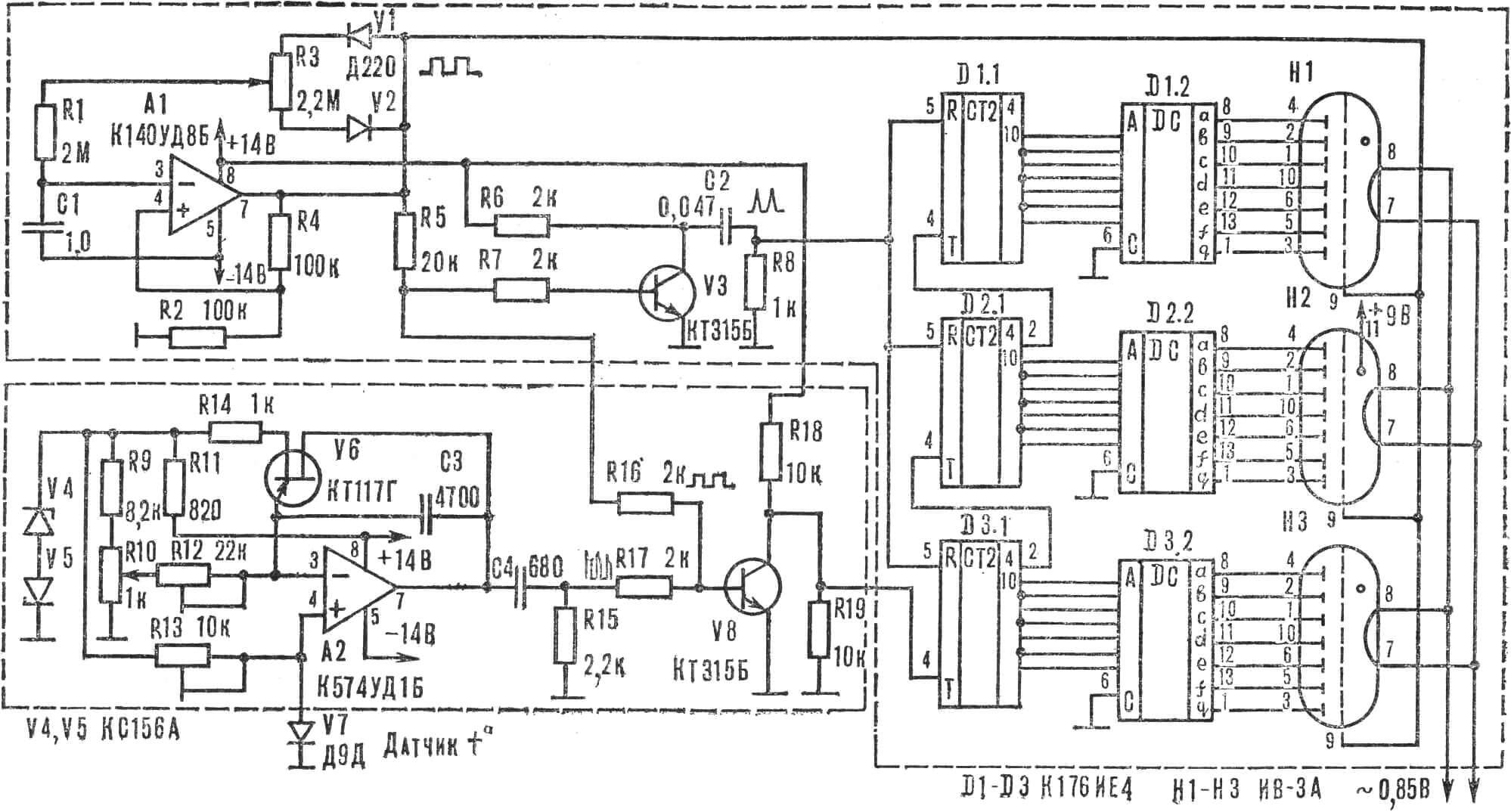
The integrator is assembled on operational amplifier A2 K574UD1B with a high voltage slew rate. This achieves high tracking speed and a conversion accuracy of 0.1°. When capacitor C3 charges to 10 V, the integrator is reset by unijunction transistor V6. The reference voltage that sets the threshold of its turn-on and stabilizes the current through diode V7 is created by two back-to-back series-connected zener diodes V4, V5.
The integrator output voltage through the differentiating circuit R15C4 goes to the current switch that forms packets of counting and indication pulses — transistor V8, on whose base the signals from the converter and the rectangular pulse generator are combined.
The generator is assembled on operational amplifier A1 K140UD8B, providing a rectangular output voltage with a period of 4 s. The pulse duty cycle is adjusted by variable resistor R3 so that the ratio of pulse duration to pause is 1:3. During the pulse duration of 1 s, information about the measured temperature is entered into the counters, and during the 3 s pause, this information is displayed on three indicators. During counting, they are locked by a 15 V voltage coming from the generator. After counting the number of pulses proportional to the measured temperature, switch V8 closes, lamps H1 — H3 display the information stored in counters D1 — D3 for 3 s — the indication period. At the end of this period, transistor V3 and the differentiating circuit R8C2 form a reset pulse. For stable operation of the generator, a memory capacitor type K73P-3 (C1) with low leakage current and high thermal stability is used.
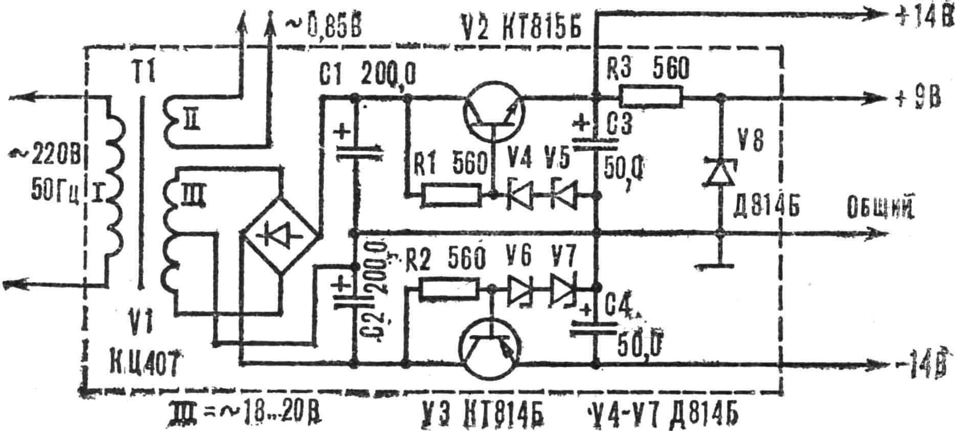
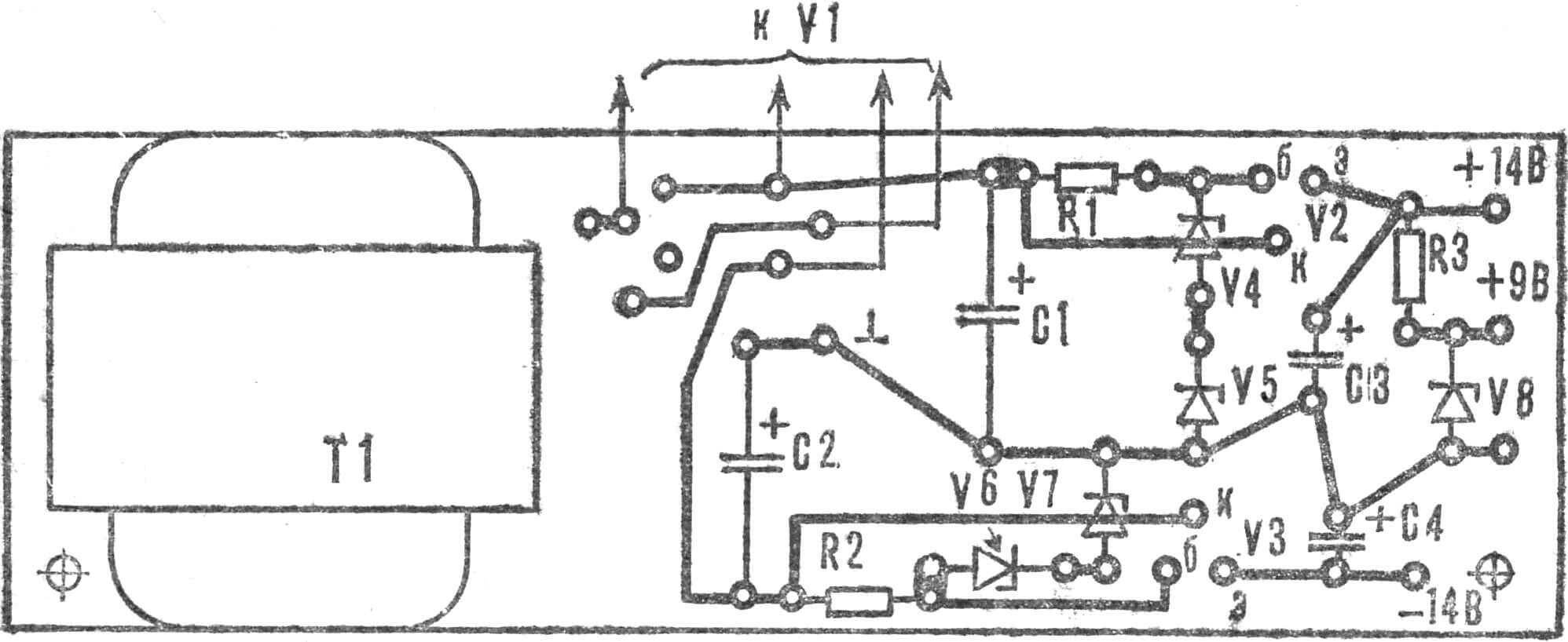
The power supply (Fig. 3) is assembled according to a conventional circuit on transistors V2, V3. The reference voltage is formed by zener diodes V4 — V8.
The transformer core T1 has a cross-section of 2.5 cm2. Its primary winding contains 5000 turns of PEV 0.1 wire. Winding II consists of two halves — 2X400 turns of PEV 0.14, winding III has 20 turns of PEV 0.31 wire. The transformer no-load current should not exceed 5 mA.
The thermometer uses fixed resistors MLT-0.125, trimmer resistors R10, R12 — SP5-3 (wire-wound, multi-turn) or similar. It is undesirable to use single-turn resistors, since the integrator trigger thresholds must be selected very accurately. Resistor R13 — SPZ-1b or SPZ-22. Capacitor C1 — K73P-3, C3 — type K10-23 or KM4, KM5. It is better to compose it from separate capacitors having TCE of different signs, so that the total TCE is close to zero. If a measurement accuracy of 0.3—0.5° is sufficient, K140UD8B op-amp can be used instead of K574UD1B.
Transistors V2, V3 of the power supply can be type KT502, KT503, KT201, KT203. The counter can be built on K155 series ICs, but then the power consumption will increase and changes will need to be made to the power supply.
The leads of diode D9 are bent to one side, soldered to an external fluoroplastic cable, and a polyvinyl chloride tube is put on up to half the diode body.
The sensor can be immersed in a conductive medium no more than half the length of its body. For operation in aggressive environments, the sensor should be protected with epoxy resin, which provides reliable insulation and good thermal conductivity, and when measuring the temperature of photo solutions, a piece of cork or foam is attached to the sensor so that it floats on the surface of the solution.
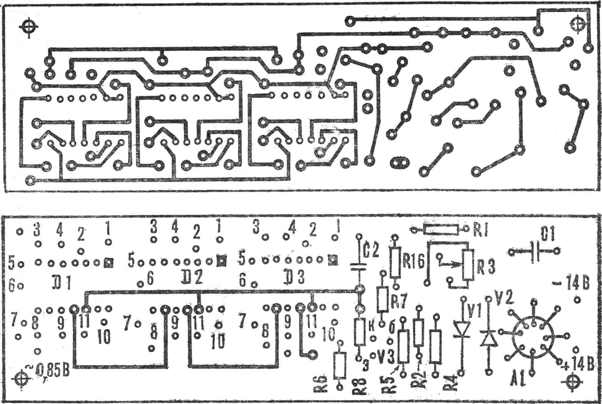
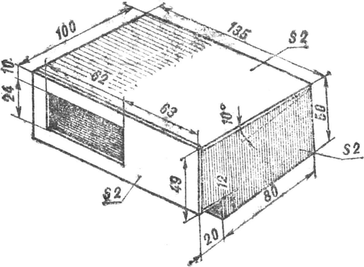
The thermometer is mounted on three boards made of 1.5 mm thick foil-clad fiberglass. On two boards measuring 130X40 mm, the rectangular pulse generator with counter and indicators (Fig. 4) and the power supply (Fig. 5) are assembled, and on the third with dimensions 80X40 mm, the temperature-to-frequency converter (Fig. 6) is made. Using brackets, the boards are attached to a getinax base measuring 130X90X3 mm and placed in a housing with external dimensions of 135X100X50 mm. It is soldered from 2 mm foil-clad fiberglass (Fig. 7) and covered with a “wood-like” film. The display slot is closed with plexiglass with a blue-green light filter. The sensor cable is wound on protrusions located on the rear wall of the device.
To achieve maximum thermometer accuracy, adjustment is carried out using digital frequency meter ChZ-32 and an industrial thermometer. When using simpler instruments, the adjustment accuracy decreases to 0.3—0.5°.
To calibrate the converter, the generator is disconnected from the base of transistor V3, and a frequency meter is connected to the collector of V8. Using trimmer resistor R13, the current through sensor V7 is set to 1 mA. Then the sensor is placed in boiling water (100° C), and variable resistor R12 sets the output frequency to 1000 Hz. Then the sensor is cooled to 0° (melting snow) and variable resistor R10 stops the integrator oscillations. These operations are repeated 3—4 times to eliminate the mutual influence of resistors R10, R12.
Then the generator is connected to the base of V8 and variable resistor R3 sets the counter reading at a temperature of 99.9° to the value 99.9. After this, the linearity of the device is checked over the entire temperature range. For example, the human body temperature is measured, comparing with the readings of a medical thermometer. If necessary, the adjustment is repeated.
THERMOMETER SPECIFICATIONS:
Temperature measurement range, °C … 0 — 99.9
Resolution, °C … 0.1
Measurement accuracy
— in range 10 — 90, °C … 0.1
— in range 0 — 10, °C … 0.5
— in range 90 — 99.9, °C … 0.3
Temperature reading time, s … 1
Temperature indication time, s … 3
Power consumption, W … 1
Dimensions, mm … 135x100x50
Weight, kg … 0.3
A. SHAMOV, G. SHIK
Recommend to read
 EVEN CHANDRAGADI
On the shore of the sea of Okhotsk, far from the regional center — the city of Magadan, located North of the village of Evensk. There are still no good roads, just on the outskirts of... AND THROUGH THE SWAMP, AND SNOW
ATVs on tires of low pressure are becoming more comfortable. If ten years ago, enthusiasts of all-terrain vehicles created mainly of three-, four - and six-wheeled vehicle, devoid of...
