The automation device I designed is intended for farmers and owners of dachas with an autonomous water supply system whose key elements are a water source (river, lake, well or borehole), an electric pump and a pressure tank. Unlike similar devices, this one not only performs the main function—controlling the electric pump—but also handles security tasks quite effectively. This versatility is achieved not by complicating the circuit but by quickly swapping sensors: besides submerged multi-level electrodes, photocells or a thin wire acting as a break detector can be used.
In a local water supply system the device acts by switching electromagnetic relay K1. The relay, powered from transformer T1 (via diode bridge VD1–VD4 and thyristor VS1, which is controlled by water-level sensor SL1), turns the pump on or off.
Suppose the tank is so low that with switch SA2 in the “Pump” position all electrodes of sensor SL1 are open. The thyristor control circuit is effectively idle. No current flows through VS1 and relay coil K1, while socket XS1 receives 220 V through normally closed contacts K1.1, so the system refills the tank. This continues until the water level reaches electrode B of sensor SL1. That is the upper limit: once reached, the thyristor turns on—current through VS1 and coil K1 pulls in the relay. Contacts K1.1 open and switch off the pump. At the same time K1.2 close, connecting electrode pair A–C of SL1 into the thyristor control circuit and keeping the water level in the tank automatically.
When the level drops below the minimum, electrode pair A–C opens. The thyristor turns off immediately and the relay drops out; its normally closed contacts then supply power to the pump. The pump runs until the tank is refilled and the system returns to waiting for the next drop. The water-level sensor consists of three L-shaped metal plates mounted on a float—an insulated base.
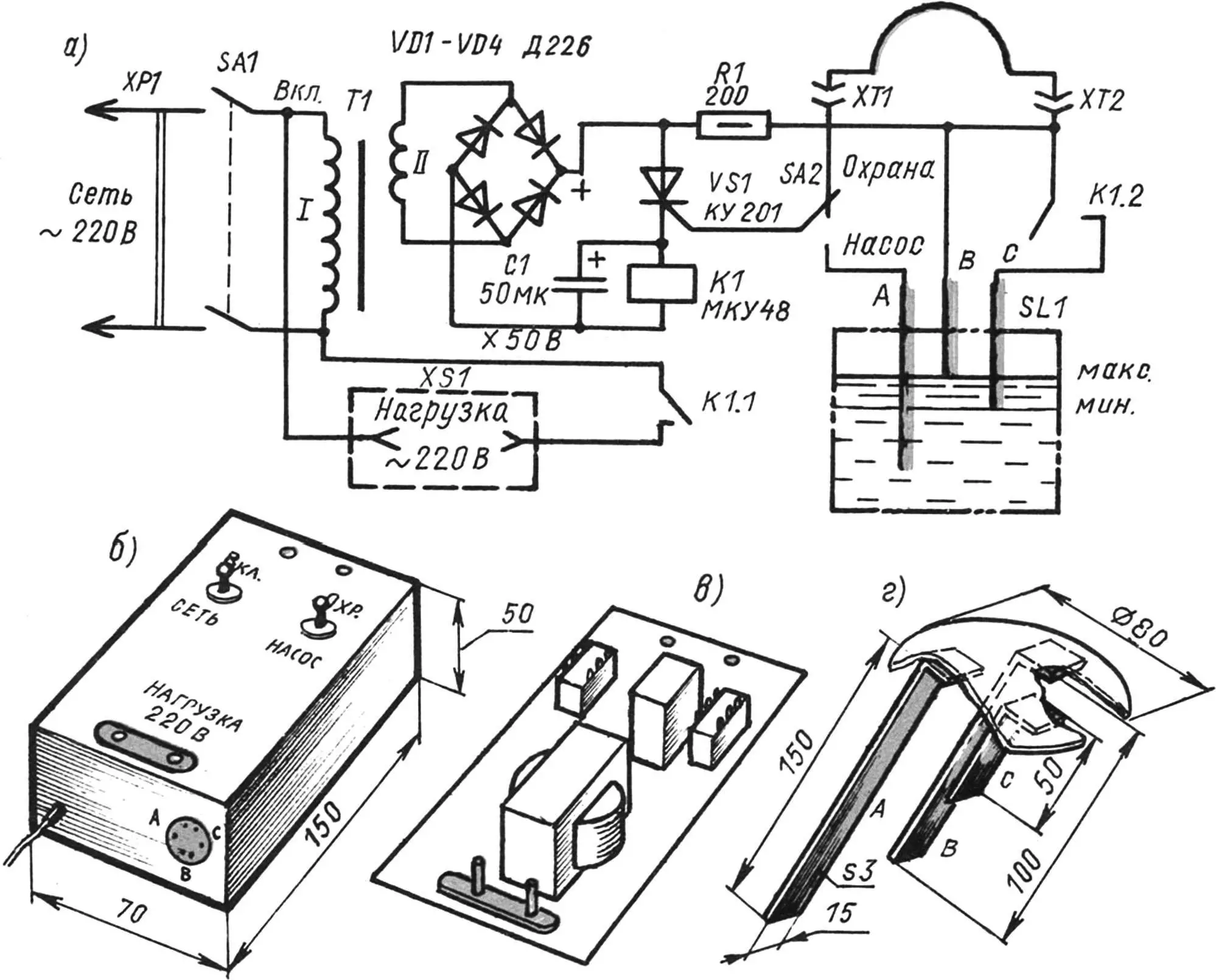
With switch SA2 in the “Security” position, the sensor is a thin concealed wire (loop) between terminals XT1 and XT2. An intact loop provides control voltage to turn on thyristor VS1 and energize the relay, which keeps contacts K1.1 open in the load supply circuit. The load is no longer the pump but a light or sound alarm (e.g. lamp, siren or bell). So when the protected area is undisturbed, there is no voltage at socket XS1 and no alarm. If the loop is broken, current through the thyristor and relay coil stops, and the alarm is powered via normally closed contacts K1.1.
Assembly does not require expensive or hard-to-find parts. Switches SA1, SA2: TV2-1 or TP1-2; rectifier diodes D226 or equivalent (or a ready-made bridge KC401…KC405). Capacitor C1: electrolytic about 50 µF, rated at least 50 V. Resistor R1: common 0.5 W type (e.g. MLT-0.5); thyristor VS1: KU201 (KU202).
Choosing the relay and a suitable transformer is trickier. If the MKU48 (12, 24 or 36 V) shown in the schematic is not available, TKE52 (TKE53) will work. Measure the relay’s pull-in voltage and select a step-down transformer to match—e.g. TN36 or even the output winding from an old tube radio.
If no suitable ready-made transformer is at hand, use any 220 V primary unit. Measure the secondary voltage, then unwind the secondary counting turns. Find the turns-per-volt ratio and wind a new secondary II to match the relay’s pull-in voltage. Connect the relay to the modified transformer via the rectifier bridge, plug into the mains, and check that contacts K1.1 operate cleanly and windings do not overheat.
The electronics are assembled on a piece of phenolic or glass-epoxy board. Use point-to-point wiring and fit the finished unit in a plastic case of suitable size.
The security loop is a thin insulated or bare wire of the required length, hidden so that intruders unaware of the system will snag and break it.
«Modelist-Konstruktor» No. 2’2000, Yu. Kochkin
Recommend to read
 A PASSENGER CAR IN THE PLOWLAND
Car enthusiasts who have dachas or homestead plots take up shovels in spring just as enthusiastically as the carless part of humanity. Meanwhile, they could quite avoid such unproductive... MAGNETIC FINGER…
I think many who have to work with small metal objects. will be useful to my "magnetic" finger, or rather — rubber fingerstall to which is glued a small square of a permanent magnet.
