For information: “Terry” — pronounced high with PLANO-convex wing profile, two-gear and low-lying, heavily mowed down by the engine. The main parameters of the model: the span of about 1000 mm, wing chord of 200 mm, length of the nose to the edge of the fuselage about 170 mm, shoulder stabilizer (“clearance” between the wing and the stabilizer) is 270 mm, the dimensions of the stabilizer 130X450 (130 mm on the chord of the rudder accounts for 30 mm). The midsection of the fuselage of about 100 mm. 65Х Model alnobetula, with the exception of the foam wing, covered with the factory thick veneer, like fake (!). Despite the use of balsa, even with a light equipment and motor 1.5 cm3 Yunior complete a lot of small model aircraft is quite significant — about 1100 But, contrary to popular belief about the critical importance of the specific load bearing surface, “Terry” surely flies even with a badly worn engine, while equipped with the standard screw from the “Junior”. The speed of flight is small, so “steer” against the strong wind of the plant difficult. But in principle this is not required, as the training model was not originally designed for stormy atmosphere. With a weak MK-17 climb rate of the machine is quite satisfactory. At desire it is possible to dramatically improve the speed (and thus improve “verosimilmente”) at the expense of speeding up of engine and selection of the propeller, but it is rather the second stage of learning.
In the air under a dual management “Terry” allows you to do with them anything (and in the good hands of the pilot and the model itself is capable of many things) — in any case, immediately after releasing the rudder, the plane quickly restores the steady horizontal flight regime. There is another important advantage of this construction — high strength, eliminating the danger of accidents.
Advantages simple model “Terry” led us to the development of its analogue, designed for fabrication from readily available materials. On the basis of increased mass Bespalova design and potential use of heavy equipment, we slightly increased all dimensions of the model, bringing the dry weight in take-off configuration up to 1350 g at an equal footing with “Terry” a specific load. Another change was the transfer of the stabilizer to the top of the fuselage (in its original form it was located in the middle of the height of the rear fuselage, appearing so very vulnerable, even with a simple revolutions on the landings).
The rest of the new machine is fully consistent with the external geometry of the aircraft-the prototype. Flights are at an increased modification with an average power engine 2.5 cm showed that in this form created from other available materials the model has preserved all its dignity. So that’s what we recommend to a wide range of newcomers-“radio operators”.
By design, the new plane does not have any “revolutionary” features, dwell on common issues is not necessary. We only note a number of noteworthy moments. The first is the introduction of detachable wing. We believe that in this case a departure from the scheme of “prototype” is justified, because initially stacked wing is much more sensitive. And the introduction of a snap connector not only simplifies the manufacturing processes, slinky and repair a “flat” of the consoles, but acts as an additional protection against breaking of the wing. The connecting pin may be wire grade optical fiber with a diameter of 3-3,5 mm. Although it is possible that any other round and flat pins.
The main parameters of the model.
Fuselage:
1 — boss (Linden), 2 — corner rounding (Linden), 3 — motor mount (plywood 5-6 mm), 4 — cover (plywood I mm n bent Linden slats 2×4 mm), 5 — inclined wall (Linden 5 mm), 6 — reinforcing cross member (Linden 12X12 mm), 7 — Board (plywood 2-3 mm), 8 — loginentry timber (pine 4Х12 mm), 9 — bracing pine (2,5x5mm), 10 — additional cross member (pine ЗХ10 mm) 11-cross member (pine 7 x 7 mm), 12 — upper panel (cardboard 0.5 mm), 13 — dorsal fin (Linden 2 mm). 14 — supporting rib of the keel (Linden 5 mm), 15 elements of a set of keel (pine, 5 mm), 16 — rudder Assembly (foam PVC trim slim pine or Linden slats and with the tight thin writing paper on epoxy resin), 17 stabilizer, 18 — rear frame (plywood 5-6 mm), 19 — lower lining section (Linden 2 mm), 20 — tool insert of the stabilizer (pine 6X6 mm), 21 — lower power stringer (pine 7X7 mm; after the Assembly model round section for R7), 22 — upper stringer (pine 6X6 mm; after the Assembly of the model to fillet section, together with the children. 12 for R7), a 23 — spacer (pine 4X4 mm), 24 — tail bracing (pine 2,5X5 mm), 25 — frame landing gear (Bubinga 6x 13 mm) 26 — shoulder mount torsion bar rack (plywood 5 mm), 27 — lower sheathing (plywood 1 mm with transverse fibers “shirts”), 28 — strengthening of the junction of the skin with stringers (curved slats 4X4 mm), 29 — steike compartment (plywood 1 mm; if necessary, to divide the upper compartment into two: under the tank and power supply equipment; you need to install the same vertical wall made of plywood, which is shown in dashed lines on the section b-B), 30 is a motor frame (plywood 2-3 mm), 31 — pin rubber loops for fixing of the wing to the fuselage (aluminum knitting needle 0 to 3 mm), 32 — top side edging (Linden 3 mm), 33 — power frame (plywood 2 mm), 34, 36 — additional frames (plywood, 1-1.5 mm), 35 — panel (pine 2.5 X 5 mm; unlike all of the braces and spacers is placed flush with the surface of the fuselage), 37 — filler engine compartment (balsa, PVC foam or light lime). If you want to increase the amount of under-wing compartment need the frame 34 to hold the sloping back under the casing 12, at the same time abolishing the additional cross member 10, and wrap to enhance the area “a” thread with glue.
The profile of the wing and its structural elements.
Wing:
1 — end gusset plate (plywood 2 mm), 2 — the oblique ending (Linden 5 mm) 3 — shelf side member (pine 3X8 mm), 4 — Polonnaruwa (plywood 1.5 mm), 5 — rib (plywood 1.5 mm), 1 6 — the leading edge (build from pine slats ЗХ15 and 7X ” X th mm), 7 — lining or filling in the section for protection of the skin from exposure rubber strip, 8 — end rib (Linden 5 mm; to facilitate the rest of the rib), | 9 – panel (plywood 1 mm), 10 — Klondike (plywood 2 mm), 11 — trailing edge (pine 5X 13 mm), 12 — insert the ferrule (ferrule brass or duralumin tube for the pin connections of the consoles, insert — lime, cheek — plywood, 2 or 1 mm; 5* a node after gluing to adjust the size of the place in the wing ; before installation, wrap the threads with glue), 13, 15 — the power of I wall (Linden 3 mm), 14 — the wall (foam PVC 3mm), 16 — 1 light weight rib (Linden 4 mm). 17 — pad (plywood I 1 mm).
Horizontal tail:
1 — groove, 2 — edge pine (5 X6 mm), 3 — filler (foam PS-4-40), 4 plastic (paper), 5 — hinge, 6 — rear flange (pine 2,5×5 mm), 7 – gain (pine 5X5 mm), 8 — wheel, 9 — under groove of the retaining pin of the stabilizer.
Vacant stabilizer:
1 — ending (Linden 5 mm), 2 — edge (pine 5Х6мм),3 — brace-rib (pine 2×5 mm), 4, 10 — amp, 5 — groove, 6 — falcinellus (pine 2X3 mm), 7 — lining (Linden 2 mm), 8 — a covering (film), 9 — rear flange (pine 4X5 mm) 11 — groove under the pin.
Another is a somewhat unusual design of the fuselage, in which the upholstery of the sides and bottom applies only to stringers and rare samotnych details. Still braces even when gluing flat panels of the sides are recessed by 2 mm. The final Assembly of the fuselage is glued together first the nasal area to the rear of the wing leading edge (more precisely, to the appropriate frame), and only then the panel can be reduced to the tail and in its place shanaytsa tail frames. Cross-struts of the fuselage bottom is also recessed by 2 mm.
Items of radio equipment are located to provide the desired balancing without lead zagruzok. By adopting a final decision on cars, they are between side frame members glued foam blocks-lodgements. If desired, of course, you can use the classic version of the mounting machines on a plywood bridges or the framework is fixed to the frame. With heavy stabilizer, power supply equipment and receiver are able to place in the first marchenhotel section (the receiver with a foam front wall of the compartment, and the block next to the fuel tank).
I would like to mention one interesting modification of this model. It is a pure glider version, in which the takeoff weight is in the range of 1000 g, and therefore the specific load on the bearing surfaces is not more than 30 g/dm2. For centering the power supply is put in place of the removed engine, and the open bow section is closed dural flap. Immediately provide at the bottom of the fuselage attachment point of the tow hook (about 10-20 mm in front of those in the figures center of gravity).
In the absence of good runway model is operated without the chassis — with it she flies great, and at landings in tall grass rack with wheels only are the “initiators” of the inversion model. The scheme of installation of the landing gear, we do not give, use well known and proven best solution used in many radio-controlled (for example, see “M-K” No. 9 1992).
V. ZAVITAEV, master of sports
Recommend to read WHO HERE HASN’T? I think that many people were trapped on their balcony, and only left him, as the handle closed behind you doors turned and ankola you, and it will not open without help from inside the... Armchair – in a rocking chair There is something in the home is very cozy in the structure itself "grandmother" a rocking chair: it is so nice to sit back and comfortably deflected. sheltered warm blanket, read a... Scroll back to top
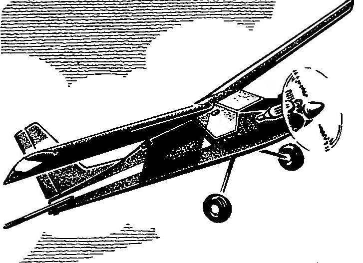
 For those who have passed the first stage of learning the art of radiopilot on the simplest gliders and pondered the project of the first motor cars will probably be interesting and useful the following information. Season 1992 among beginners-“radio operators” in Moscow conditionally passed under the sign “Terry” (so-called set-make a learning engine model by “Graupner”) — so a large popularity of the scheme is a good small model.