MT has become a truly indispensable mechanical assistant to undertake any works on the land. After all, it is now possible without a mechanical connection to connect a lawn mower, and other agricultural implement with a hydraulic drive.
Finally, we should mention another obvious advantage of the proposed design over other MT: with the use of hydraulic motors eliminates the need to… the brakes. One only has to reduce oil flow — and please: braking performance, as they say, a hundred. And when installing the arms control valves in the neutral position (especially for options distributors 4/3 and 4/4 with the connection on the tank discharge line and locked elbows at the middle position of the valve) is actually full wheel lock. This mode may be used for emergency braking and almost trouble-free “Parking” brake.
Frame mini-tractor welded. The necessary strength and adaptability are achieved through the use of steel tubes of rectangular cross section, fatty scarves and soundness of the structure, successfully operating on all kinds of deformation. Selected according to the loads and sizes of bearing elements. In particular, the spinal beam is a 990-mm section of steel thick-walled square tube 60×60 mm. Segments of same tube with the corresponding length (see Fig .) serve as load-bearing elements of the suspension axles of the rear wheels and the mounting of the hitch mechanism. But for the sub-frame material selected is different. Here already used steel pipe rectangular 60х35 mm.
In the middle of the transverse sub-frame welded bushing axis of oscillation of the front axle. It is executed from Steel 45 with slots for radial ball bearings No. 80206.
The shape and dimensions of the brackets of the power unit and cylinder mounts and their mounting location are determined, based on what the SA and the cylinder of the homebrew available. And the material is 5 mm sheet St 3.
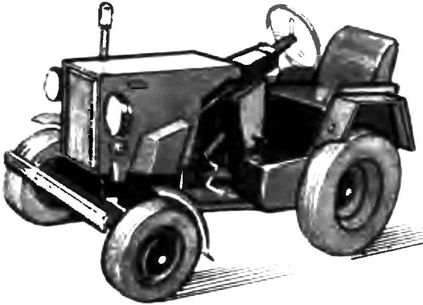
The location of the engine and hydraulics on the frame MT (the front axle with the steering column and fascia removed):
1 — arm control valves (means and rotation of the rear wheels), 2 — two chetyrehlistnyj three-position distributor (symmetrical to the longitudinal axis of the MT) with control handles, 3 — gear type pump NSH-50 constant performance, 4 — hydraulic motors with reversing flow, 5 — engine, 6 — frame mini-tractors, 7 — drive roller chains (PR-15,875) , 8 — hose, high-pressure, shut-off devices, 9 — rear wheel with pneumatic tire is 6.5 — 16″, 10 gas tanks, 11 — seat with backrest.
Homemade front axle with variable track width. The latter is achieved by introducing into the design of the right and left nodes of the slewing rack instead of the usual axes with rotary axles, and also due to the different mutual arrangement of the discs and rims of wheels, as shown in the figure.
About features of implementation of base-swivel consider it appropriate to tell a little rounder. His fist is very good swivel pin must be cut off and welded to the corresponding end of the pivoting I-beam steel tube of rectangular cross section 60х35 mm, having a length of 500 mm. the Second end of the beam is welded to the pipe sleeve (Steel 45) of the slewing rack.
Start a new design element, it may be considered necessary. Now, another important and critical parts of the slewing rack with two diametrically disposed keyways. Material for its manufacture is the same Steel 45. On the upper end of the strut is threaded M20, and thoroughly welded to the lower sleeve half shaft of Steel 45.
Very homemade driveshaft (Steel 50), with seats under the bearings 305 and 206 for installation on its front wheel from the sidecar FDD bus 5.0 to 10″. In the hub the axis is fixed quite firmly, having on its end a M20 thread on which is screwed a corresponding nut with planted under her washer Grover.
Hydraulics and kinematics of the powertrain:
1 — power unit (motorized FDD), 2 — front wheel tire and a 5.0—10″ (motorized FDD, 2 PCs.), 3 — elastic coupling (homemade), 4 — gear pump NSH-50 constant performance (from the farm), 5 — star leading Z=12 drive roller chain PR-15,875 (2 piece), 6 — hydraulic motor with reversible air flow (farm equipment, 2 PCs.), 7 sprocket Z=28 roller chain drive PR-15,875 (2 PCs.) 8 — sprocket Z=14 roller drive chain PR-19,05 (2 pieces) 9 “rocker” suspension axle rear wheel (homemade, 2 pieces), 10 — valve 4/3-controlled arm with a locking mechanism (farm equipment, 2 PCs), 11 — sprocket Z=54 driving roller chain PR-19,05 (2 PCs), 12 — wheel rear tire is 6.5—16″ (from front axle of tractor T-28, T-40, etc., 2 PCs.) 13 — fuel tanks (self-made from canisters suitable container, 2 PCs.), 14 — sprocket Z=14 roller drive chain PR-12,7 (milling cutter) 15 — hose, high-pressure (shut-off device conventionally not shown).
Depending on the desired height of the front axle pornopolane rack can be fastened to any of the level two thrust washers. The swivel arms (illustrations not shown) also move in the keyway groove to the appropriate place, and then rigidly fixed mortise with screws M12 (similar to the installation of the thrust rings). The steering mechanism is taken from written off cars GAZ-51.
Frame mini-tractor:
1 — Bush axis of oscillation of the front axle (warna, Steel 45), 2 — under engine frame (welded, tubular steel □ 60х35 mm), 3 — brackets of the power unit, front (shape and dimensions at the place of installation of CA 5-mm St3), 4 — mounting brackets of the power unit, tail (shape and dimensions at the place of installation of CA 5-mm St3), 5 — beam suspension axle of the rear wheels (strong cut pipe □ 60×60 mm), 6 — bracket “rocking” the installation (of 5-mm St3, 2), 7 — spinal beam (steel thick-walled pipe □ 60×60 mm), 8 — the solitaire (of 5-mm St3, 12 pieces), 9 — beam attachment of the hitch mechanism (steel pipe □ 60×60 mm), 10 — bracket, main (5 mm St3, 6 PCs), 11 — mounting bracket of the hydraulic cylinder (for the hitch mechanism, the shape and size from the 5-mm St3).
“The rocker” suspension axle rear wheel:
1 sleeve (Steel 45), 2 — sector distribution (5-mm sheet St3), 3 — steel pipe □ 60х35 mm, 4 — axle bushing rear-wheel (Steel 45).
The techniques of gauge change by permuting the elements of the wheel.
The axle shaft of the front wheel.
The base-swivel front wheel (rotary beam front axle is conventionally rotated 5° to the vertical axis, “fist” and thrust not shown):
1 — bushing axle, 2 — the thrust pieces (2), 3 — the bearing № 8206 ball thrust, single (2 PCs), 4 — Bush supporting-swivel, weld-on, 5 — bearing No. 80206 ball, single row, with protective washers (12 PCs), 6 — support-and-swivel stand with two diametrically disposed keyways, 7 — rotary beam front axle, 8 bolt M12 flush (2 piece).
Chain link removable grouser:
1 — chain mounting (stretched to the right while pumping the wheels), 2 — M10 studs, 3 nuts M10, 4 — plate lug (5 mm St3), 5 — chain mounting (stretched to the left when swapping wheel), t is the distance equal to the pitch of the chain.
Wheel hub rear (leading) wheels.
Half shaft of the rear wheel.
The axis of rocking.
Suspension of the axles rear (leading) wheels are made by “rocking” is a special rotary mechanisms pivotally bolted to the frame MT (beam suspension) and allowing at the same time easily and quickly make a clearance. “Rocking” (see Fig.) reliable, well-proven in practice, steel pipe rectangular 60х35 mm with welded at the ends of the sleeves.
The latter is made of Steel 45 with sockets to be installed in their ball radial single-row bearings with protective washers. And for bushings with an external diameter of 70 mm is the best fit bearings No. 80206 (2 pieces) and another, with an external diameter of 80 mm, No. 80207 (also 2 pieces). On top of the smaller bushing is equipped with a welded thereto a mounting sector of 5-mm sheet St 3, which was prudently done 5-7 holes Ø 14 mm for fixing the “rocking” in a particular position relative to the frame MT (changes ground clearance of the mini-tractor).
The rocking axis as the axle shaft of the rear wheels, Steel 40KHN. Can be used here for standardization and quality carbon structural Steel 45 Configuration and dimensions of these undeniably responsible, details clear from the accompanying illustrations.
Hydraulics and kinematics of the transmission (see Fig.) particular difficulties for the understanding and production also, apparently, not cause. Life and sets the tone for here the power unit. In this embodiment of the motorized FDD, although success will also fit any other SA power 14-18 HP In particular, have passed the strict test design with the power unit (though somewhat modified) of the scooter.
On the output shaft CA is installed on the flexible coupling. About how such do it yourself, the magazine reported repeatedly (see, for example, “M-K” 3’92). Through the clutch torque is transmitted to drive gear pump brand NSH-50, which creates the oil pressure in the hydraulic system equal to one hundred atmospheres.
As practice shows, the capacity of this pump is sufficient to ensure the normal operation not only of motors, actuating (by means of dual chain drives) the drive wheels. It will be enough for another variant of MT (with the power cylinder of the hitch mechanism) and also for motor on any of the implements for mini tractor. In the illustrations these auxiliary nodes required for the additional dispenser not shown.
Used in the construction of MT motors – from specialized machinery to combat icing on the roads (sand spreaders). But it is possible and from other equipment. It is important only that the capacity of each of the motors was about 3.5 kW, and rotation speed – 2200 rpm.
In this version of the mini-tractor, two chetyrehlistnyj three-position distributor (decommissioned agricultural equipment) with control arms. Located symmetrically to the longitudinal axis of MT, they constitute a separate unit. Can be recommended for use in the construction of improvised MT and other types of dispensers. For example, mnogostanochnikov device with a single (cast) body, designed to direct oil flow from the pump in the power cylinders (hydraulic motors) or the bypass, as well as for automatic switching of the oil flow to the bypass after execution of military operations – from excavator MTZ-80.
Sprocket for chain drives, it is desirable to pick ready: from old trucks and tractors, motorcycles, scooters or make them yourself (see “M-K” 2’86). Perhaps a good “compromise” option: when their hands are made only of the hub. As shown in the example, driven sprocket Z 54 (see Fig.).
Homemade are the rear hub (top), the wheels. The dimensions and configuration of the clear from the drawing. As for the wheels, they are from a tractor T-28 or T-40 – driven (front), tyre 6,5-16″. Their design allows you to easily change the track by permutation of the elements of wheels and a 180° rotation of the entire wheel Assembly.
Lugs at the mini-tractor is rather unusual. At the heart of them – the same two closed chains (“wireline”, or any other large-step). The perimeter of each 50 mm less linemachines (outer) circumference of the wheel.
Between the chains are hard links of lugs, each of which is welded (in the form of a gable “micro-roofs”) design, consisting of a pair of rectangular plates of size 40х100 mm (of 5 mm STZ) and two threaded rods M10 length 150 mm Protruding on both sides from the “microcrush” the ends of the pins are inserted into the rings of the chains and tightly tightening the last nuts M10.
The thus prepared circuit with cleats, tightened between them, put on some lowered wheel. Then using the pump chamber pressure of the wheel lift.
In conclusion, a few words about the mounted and trailed implements used when working on the mini tractor. Plowing is done using dvuhgorbogo plough, made of skimmers with equipping their field Board and increased blade. Soil cultivation, cutting ridges, planting of potato are practically the same as described in “M-K” 3’92. But the mount cultivators on a suspension frame is somewhat different — with special bushings. Snow provides for the installation of the “bulldozer” of a knife-blade, for raising and lowering which carries the power cylinder. And the widely used hay mower with hydraulic drive and rake.
To perform a number of specific works will be connected to a mini-tractor cutter or circular saw. Well there suddenly a need to bring-to take something on the farm – rescue tow truck. At the same transport speed when you give all power to one drive wheel mini tractor (when the second rear from the hydraulic system disconnected) can reach 35 km/h!
MAIN TECHNICAL CHARACTERISTICS
Overall dimensions (with the clearance 320 mm), mm: 1950х1000х1350
Base (the clearance 320 mm), mm: 1200
Track (limits of change) mm: 800-1216
Minimum turning radius: virtually on the spot
Clearance (limits of change) mm: 0-800
Powertrain: from sidecar FDD (or other equipment power 14-18 HP)
Hydraulic pump: NSH—50
Motors: 2×4,75 HP + provision for mounted guns
The range of working speeds, km/h: 2-15
The oil pressure in the hydraulic system, ATM: 100
V. MEZENTSEV, Amateur designer;
N. KOCHETOV, our special. Q. Naberezhnye Chelny
Recommend to read GLIDER WITHOUT SECRETS Letters a lot. One of them is to "brand" the forms of various enterprises and institutions, others on pieces of paper torn from a student notebook. But the questions are all about the... UNROYAL DEBUT “THE ROYAL TIGER” In August 1942, the armaments Department of the land forces of the Wehrmacht developed tactical and technical requirements for a heavy tank designed in the future to replace the recently...