However, it turns out, there may be fundamental changes. Of course, once such a categorical claim is impossible: like all such, innovation must pass the stage of working out on sports cars. But for theoretical reasons, the new proposed scheme is more efficient than the traditional, and perhaps her future auromodele.
The essence of novelty — in the output stabilizing surface from the zone of air flow from the drive screw. This is achieved in the simplest way: tail boom instead be a continuation of the motor is transferred downward and is located at the surface of the earth. It is very important that the stabilizer, in addition to its leaving the areas of slipstream, the motion of aeromodel will go on the height from the track surface of the track, commensurate with its chord. This means that in the case of the presence of the stabilizer is positive (upward) lift force you can count on ground effect! The profitability of such a situation not only in the reduction of aerodynamic drag, but the damping of the vertical oscillations of the tail section. The fact that in our case, by reducing the location of the stabilizer plus the vertical force will be formed not only due to the increase of angle of attack, but also “compressible” screen “cushion”. As effective will be the action of forces when lifting the tail loss of the load-bearing properties are more pronounced than without the influence of the earth’s surface.
In a number of publications devoted to the design principles of auromodele, you can find remarks about what the aerodynamic improvement of this technology is almost meaningless — in the absence of gross errors in the contours of the cars is still overwhelming all the rest of the increase in the resistance somehow gives one cord thread with the suspension units. All this is true. However, focusing on maximum speed-in and competitive conditions, it is impossible to neglect anything, even the crumbs of reserves.
R and S. 1. The General character of the air flow passing through the propeller disk (stored as for the operating conditions of the screw in place and in motion).
R and S. 2. Wrap classic aeromodel flow from the rotor.
A — balanced steady-state driving mode, B — mode transient. Shaded “washed” the surface creates a sharply increased flow resistance, so as abecause high-speed flow from the rotor. The stabilizer does not fulfill its functions as it is located in the center of the stream.
R and S. 3. The flow of aeromodel new type.
A — steady state of motion, B — transient. In comparison with the classical model, the area of the “washed” surface is significantly reduced, respectively, and less aerodynamic loss. The stabilizer is effective, as it flows about a direct, non-rejected air flow.
R and S. 5. The flow of aeromodel new type (top view). The whole area of the stabilizer is effectively damping the oscillations of the body during movement.
R and S. 4. Wrap classic aeromodel flow from the rotor. There is a manifest need in the stabilizer of a large area and scope.
Zone I is “washed”, ineffective, introducing only incremental aerodynamic resistance area of the stabilizer area II effective area. The diagram shows the model from above.
R and S. 6. Comparison of the flow around the wing-like plate (stabiliser) in a free air stream (A) and in the presence of the screen or the surface of the earth (B). In the first case, the lifting force of the plate is a function of the angle of attack at a constant flow rate, while the second also depends on the relative distance from the screen.
Fig. 7. Diagram showing the principle of creating an increased lifting force on the stabilizer in the presence of the screen. The acceleration of flow down the tail of the profile, “erectitude” adprofile part of the flow, explains the effect of reducing aerodynamic drag.
Fig. 8. The design options of the stabilizer racing aeromodel using the on-screen effect. A — flat stabilizer and B — stabilizer with the fracture (applied at the high position of the tail boom case). In any case, the square of the stabilizer should be placed at a minimum height from the ground, eliminating the touch of the ground the tail wheel is only a small deviation of the axis of the body from the estimated position in the race.
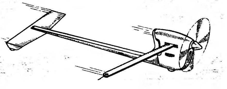
R and p. 9. Racing aeromobil is a new type micro motor internal combustion work.
In our case, the gain in the sense of aerodynamic resistance obtained in two ways. First, as already mentioned, is due to the increase in the efficiency of the damping properties of the stabilizer, and therefore there is the possibility of a sharp decline in its surface. The second option in the output of almost all model elements from the zone of the jet for a propeller in the unperturbed region (with the exception of the engine cowling, and partially cord straps). The latter technique can be considered much more effective to reduce the resistance, rather than all work on the beautification of the forms vartuli classical type. The fact that the improvement of the aerodynamic contours may winnings, only measured the percent resistance, and the output of the air flow is almost two-fold reduction. In fact, forcing the flow from the rotor in terms of the classical model to wash all surfaces, we do the same as if installed on the machine is a kind of air brakes! In reasoning it is important to note that because of the nature of Moto installations of auromodele use propellers with small diameters, whereby to obtain the desired thrust, the rate of drop must be much greater than the speed of the model itself.
From the structural point of view, the new technique is no different from the familiar to avtomodelistov. It is possible, with the proposed layout of machines may experience problems only when rendering approach to the adjustment screw compression ratio of the engine. However, this problem is easily solved if the provision on the head of the adjusting screw, the large diameter washer with knurling on the outer edge. On the assembled model, the washer should be slightly over the edge of the fairing of the engine then the adjustment will be even more convenient than conventional options with an auxiliary key, or the classic Phillips screw.
The new model has a feature and balancing. In order to achieve defined display effect on the stabilizer to the reduced area, it is necessary to load sufficiently, in the sense of lift on the calculated driving mode. This can be achieved only by the position of the centre of gravity of the machine, is displaced backward relative to the fulcrum — axis of rotation of the main wheels. Download tail of the aircar is highly undesirable, since any increase in moment of inertia about the transverse axis of the model at once destroys all the achievements of aerodynamics, and damping the chance of vibrations is ineffective and slow. So, the most expedient solution is to shift the axis of the front wheels forward at maximum facilitation of the tail of the car.
The rest of the balancing remain unchanged in comparison with models of classic aircraft type.
V. ZAVITAEV, design engineer
Recommend to read ASSISTANT PAINTER While all kinds of painting works are widely used fur or foam rollers. To remove the excess paint, apply a variety of devices, such as a perforated or solid plate, mesh. Here's another... THE ENGINE OF THE “BURAN”: REVEAL RESERVES The engine RMZ-640 "Buran" Rybinsk engine production plant is widely used not only on the same snowmobile, but deltalyo. However, if a separate snowmobile owners its characteristics... Scroll back to top
 In the competition of young avtomodelistov as the winter sports season and summer now dominates the aviation scheme snowmobiles and cars. Their scheme is already thoroughly known and, seemingly, has already passed all stages of perfection. Studied and worked out every knot simple models, clear design principles from the point of view of simplicity and reliability, stability of motion and speed of the turn.