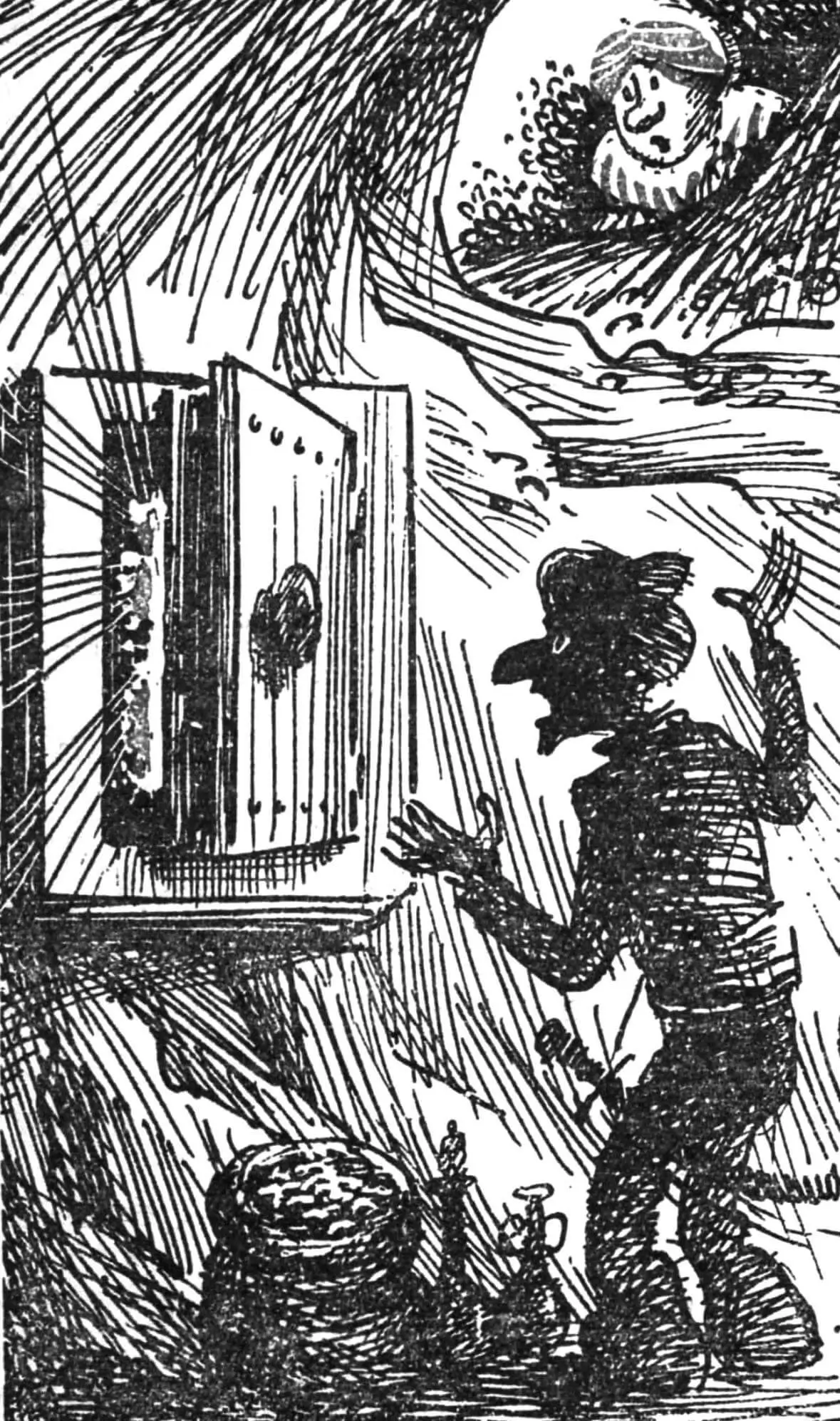
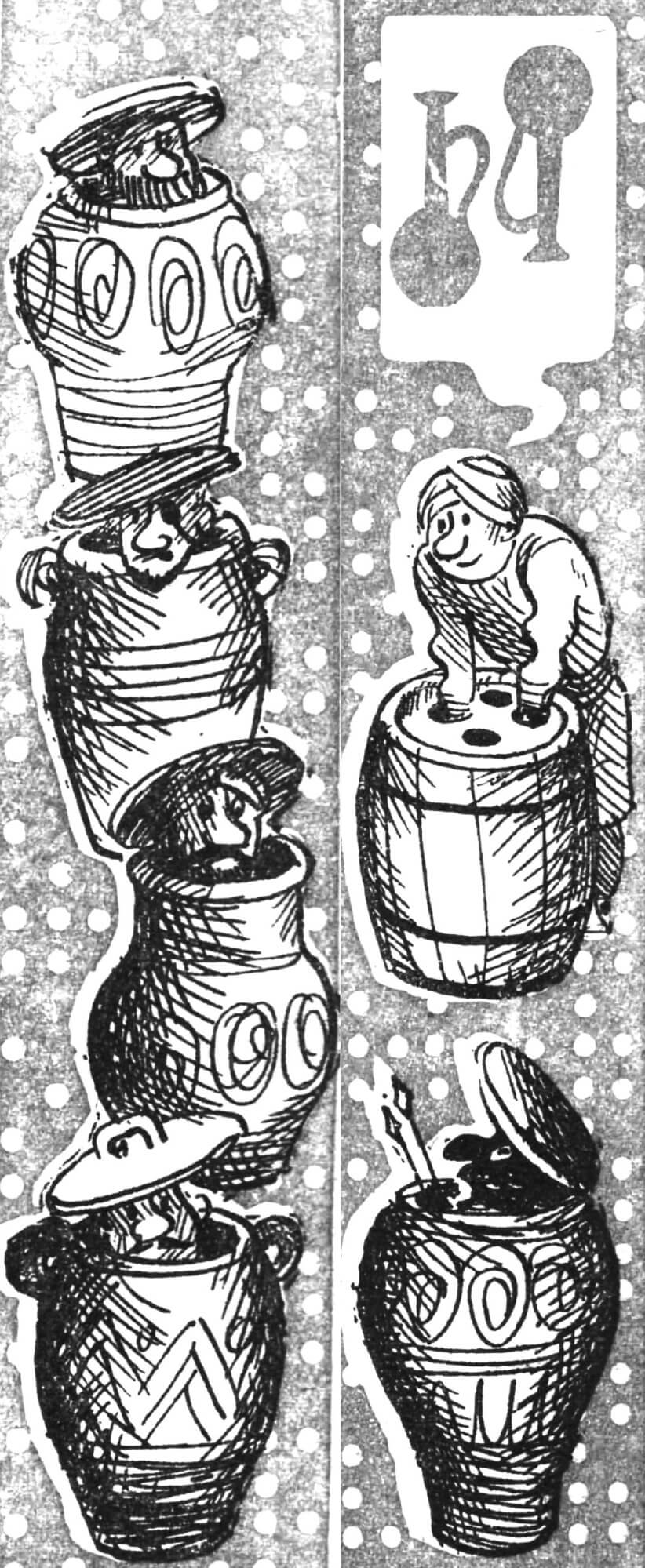
“Open Sesame” — with these words, the resourceful and brave Ali Baba opened the magic door to the cave with treasures. Let’s imagine that Ali Baba is solving a more difficult task — trying to open the door to another cave, the entrance to which is blocked by a magic barrel. It can rotate around a vertical axis, and four identical, symmetrically located holes are punched in its lid. Under each of them in the barrel there is a vessel, for example a jug. By putting a hand into the hole, one can determine by touch whether it stands with the neck up or down. It’s dark in the cave, and nothing can be seen through the barrel’s holes.
By putting both hands into the barrel, one can turn over one or two vessels. After the hands are removed from the holes, the barrel begins to rotate rapidly. After some time, it stops in a random position. Through any two holes, Ali Baba can again manipulate the vessels until they can be arranged the same way — with necks up or down. Only then will the magic door open.
Let’s try to formulate an algorithm for opening the door — a sequence of actions that, with any initial arrangement of vessels and with any variants of barrel stops, will ensure the door opens after a certain, predetermined number of moves (the example with the barrel and the description of the algorithm are borrowed from the book by V. Kasatkin “Seven Problems in Cybernetics”. Kiev, “Vyshcha Shkola”, 1975).
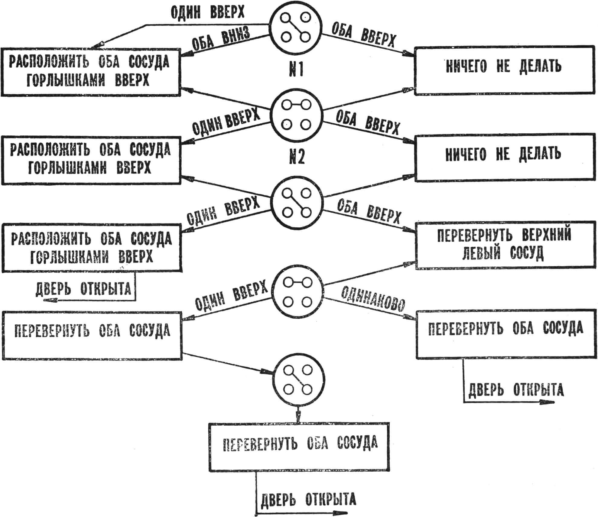
By putting hands into the barrel’s holes, a person first recognizes the position of two vessels, and then turns over one or both (or doesn’t turn over at all). We’ll call the first action a recognizer, the second — an operator. Obviously, the algorithm for opening the door will consist of a sequence of the first and second. Let’s describe such an algorithm in the form of a graph diagram (Fig. 1), in which recognizers are denoted by circles, and operators — by rectangles. Two such symbols following each other we’ll call a work cycle.
The first recognition is carried out diagonally (circle No. 1). The holes into which the hands are lowered are connected by a line. If only one jug is positioned with the neck up, then the second one must be turned over; if both vessels have their necks facing down — both are turned over; in the normal position, nothing needs to be done.
The second recognition (after the barrel rotates) is carried out using circle No. 2 (hands are passed into the two upper holes). The order of operations is similar to the previous one. Thus, after two work cycles, three of the four jugs will take the normal position — two diagonally and one on one of the sides of the diagram.
We again apply (after the barrel rotates and stops) recognizer No. 1. What do we have in the barrel? If one of the vessels is positioned with the neck down (the last of the four), we’ll turn it over — and the door is open. If both vessels have their necks facing up, then the upper left one needs to be turned over (according to the graph diagram). Now on one side two vessels are positioned with necks up, and on the other — with necks down.
After the next barrel rotation, we apply the variant with circle No. 2. If both jugs are placed the same way, they are turned over (since the other two vessels were in the opposite position). The door is open.
Suppose one of the vessels is installed with the neck up. Then both vessels also need to be turned over. Now along any of the two diagonals they will be arranged the same way.
The next cycle begins with recognizer No. 1. Regardless of the result of our “research” in the barrel, the operator “turn both over” is applied: the door is open. Thus, using the described algorithm, it is possible to open the door to the cave in a maximum of 5 cycles.
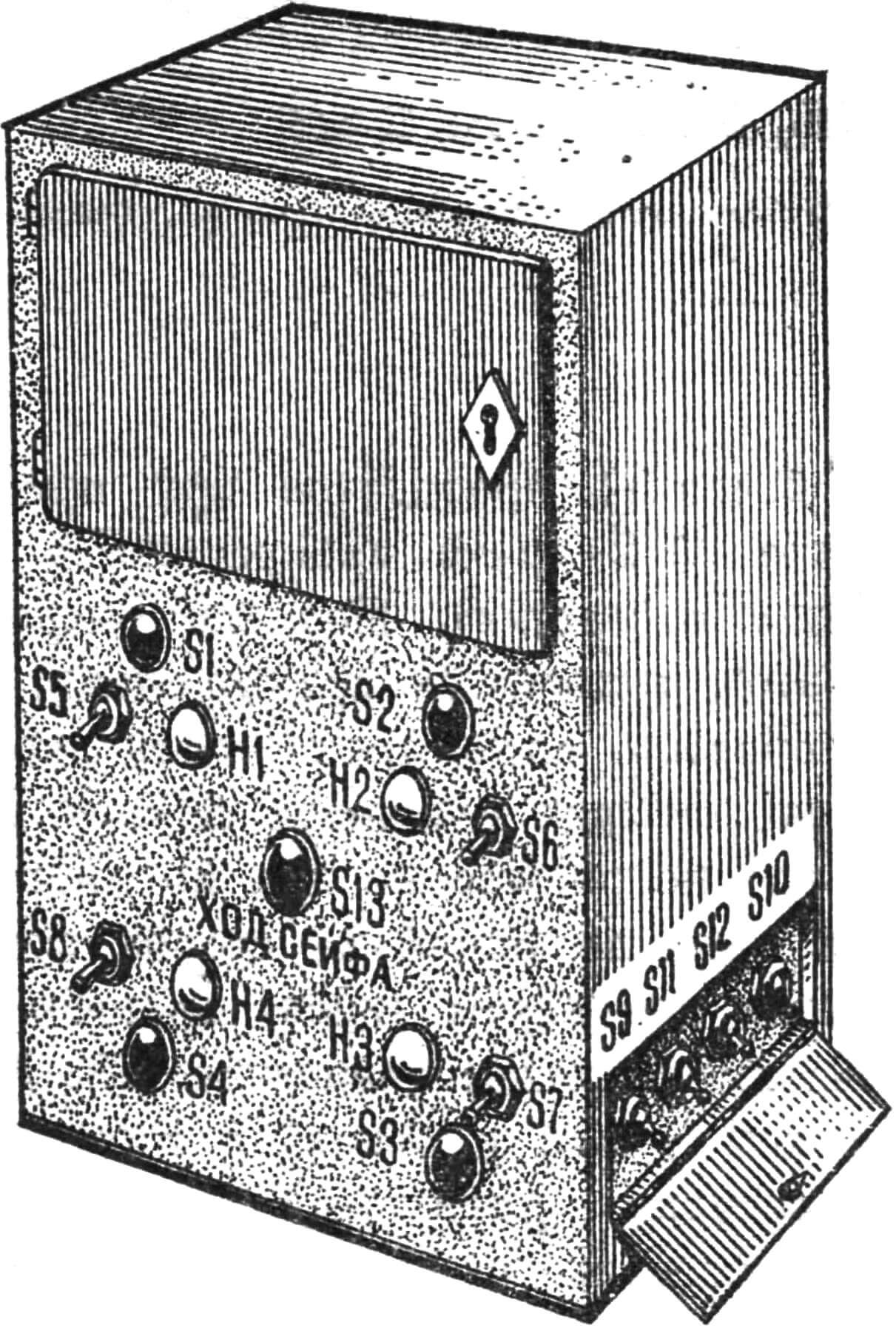
Knowing the principle of operation and the algorithm for opening the barrel, let’s construct a similar cybernetic lock for a safe (Fig. 2).
In the upper part of the body there is a door. Four light bulbs are mounted under it — they play the role of vessels. Next to each one there is a button, by pressing it (similar to putting hands into the barrel), one can find out whether the lamp is on (vessel with neck up) or not (vessel with neck down). In addition, there is a toggle switch near each lamp, by switching which one can change its state (turn over the vessel).
Another button is at the bottom of the body. By pressing it, the barrel is made to “rotate” (the states of the lamps change). Four more toggle switches are hidden on the left side panel under the cover. With their help, the lock code is set — the initial state of the lamps.
The safe door will open only when it is possible to connect or disconnect all lamps.
Before considering the operation of the device, familiarize yourself with the design of the rotating disks. They are made of getinax or glass-textolite foil-clad on both sides. On one side (denoted by the number 1) there are 4 concentric circular strips. The other side of the disk is divided into 4 identical sectors (metal foil about 0.5 mm wide in the gaps between the strips and sectors is removed). Each circular strip on one side of the disk is connected to a sector on the other, denoted by the same number (Fig. 3).
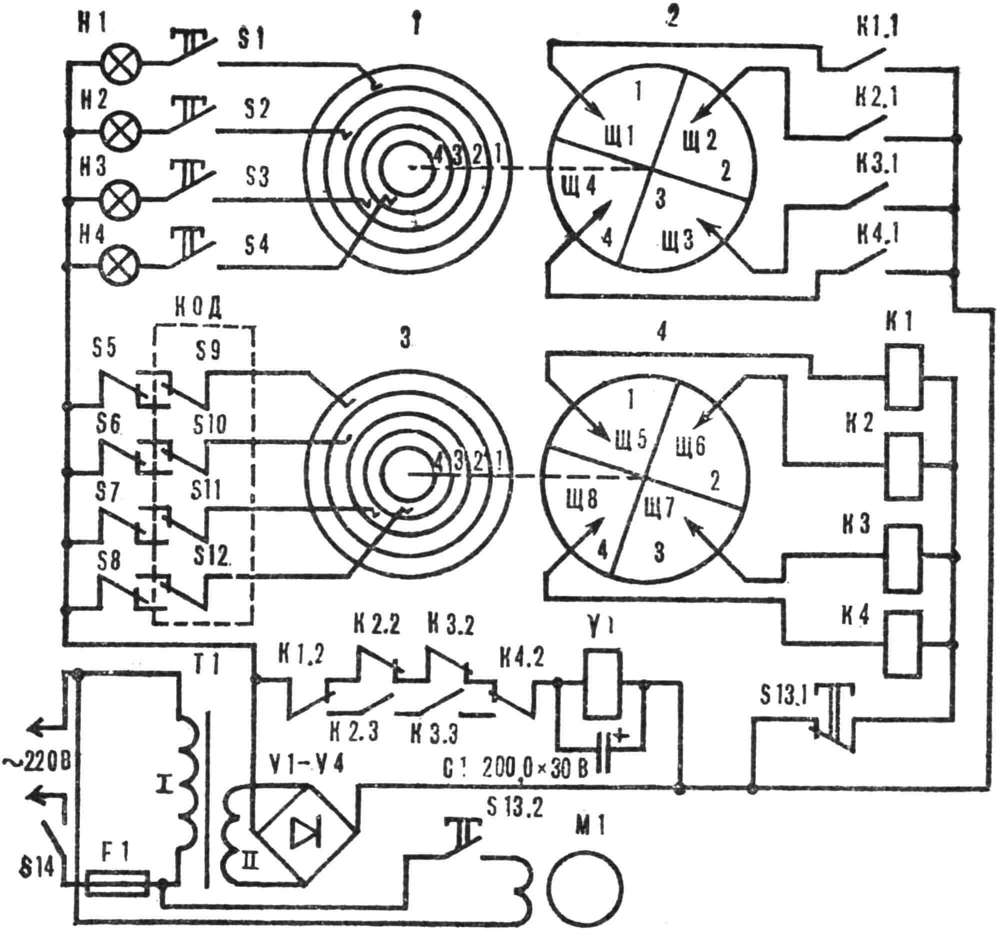
When the disk rotates, brushes slide along it. On side 1 they are placed arbitrarily, and on the second the places of their contact are equidistant from each other. Both disks are mounted on the motor shaft so that each sector of the first disk is exactly opposite the corresponding sector of the second disk (when looking along the direction of the motor shaft).
Let’s assume that the safe code is set by toggle switches S10 and S11 (lamps H2 and H3 are on). A person presses button S13 “Safe move” (we’ll call this button based on the fact that for each person’s move the safe lock responds with “its own” move). Contact S13.2 closes the power circuit of electric motor M1, and the disks fixed on its shaft begin to rotate. While they are moving, S13.1 breaks the power circuit of relays K1—K4. Suppose the first disk stopped in such a way (disk stop is a random event depending on the time of pressing button S13) that brush Sh1 is on the third, Sh2 — on the fourth, Sh3 — on the first and Sh4 — on the second sector. Accordingly, on the second disk brush Sh5 is on the third, Sh6 — on the fourth, Sh7 — on the first and Sh8 — on the second sector.
When button S13 is released, the power circuit of relays K1 and K4 closes.
According to the algorithm, we apply recognizer No. 1 — press buttons S1 and S3. Lamp H3 lights up. Then, according to the graph diagram, we apply the operator “both vessels with necks up”: we switch toggle switch S5.
We press button S13 again and then follow the algorithm instructions.
As soon as all lamps are connected (relays K1—K4 operate) or, conversely, disconnected (no relay works), through a logical chain consisting of contacts K1.2, K2.2, K2.3, K3.2, K3.3, K4.2, electromagnet Y1 is connected to the current source, and the safe door latch opens.
In our example, for this it is sufficient that toggle switches S5 and S8 are on (all lamps are lit) or S6 and S7 (all lamps are off).
The code can be changed before each demonstration of the safe’s operation. And in order to make it difficult to peek at the lock code when opening the side cover, the switches are arranged “mixed up” (for example, S7, S5, S8, S6).
After the switches located on the front panel are set to the initial position (handles S5—S8 — down), the safe lock is ready for further operation.
The following parts are used in the device: relays K1, K4 — RES9 (passport RS4.524.201); K2, K3 — RES22 (passport RF4.500.131); M1 — electric motor DSD-60; buttons S1 — S4 — K1, S13 — KM-2; switches S5 — S12 — MT1, S14 — T1; lamps H1—H4—SM26-5.
The power transformer core is assembled from Ш20X20 mm plates. The mains winding contains 2750 turns of PEL 0.15 wire, winding II — 300 turns of PEL 0.5 wire. The winding of relay RKM is used as electromagnet Y1. A metal rod connected to the armature of this relay plays the role of the lock latch. A spring is put on the door axis, which opens the door when the latch is retracted.
The safe with a cybernetic lock has one drawback: the device does not “monitor” a person’s actions and blindly follows its program. Therefore, the device can easily be “confused” by violating the rules of handling it. Suppose a person presses two buttons, finds out the state of the corresponding lamps and performs toggle switching. Then, without pressing the “Safe move” button (that is, without changing the state of the lamps), presses two other buttons, finds out the state of other lamps and by switching toggles brings all lamps to the same position. Thus, the lock opens by simply selecting switch positions, and the whole idea of the safe opening algorithm loses its meaning.
However, changes can be provided in the lock circuit that do not allow outsiders to violate the rules of handling the safe, excluding the possibility of selecting a combination of switch positions.
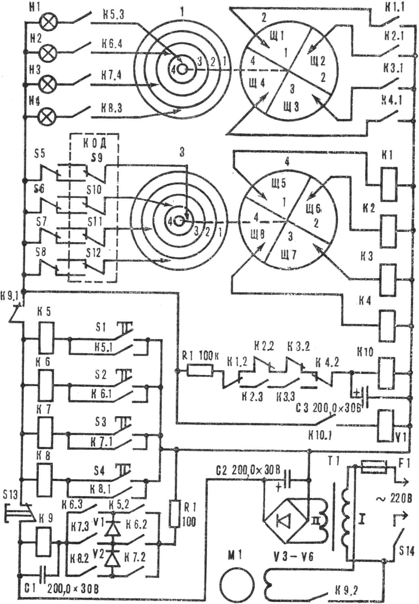
The circuit of the complicated cybernetic lock is shown in Figure 4. Blocking of incorrect human actions is carried out as follows. After 1—1.5 s (this time is selected when adjusting the device) after a person pressed two buttons and saw whether the corresponding lamps are lit or not (performed recognition), H1 — H4 are turned off. If a person now presses other buttons (violating the rules), they will not be able to get information about the state of other lamps.
Simultaneously with the lamps H1—H4 going out, the electric motor rotating the disk is turned on: thereby the state of the lamps will change. The motor works until the “Safe move” button is pressed. After that, H1—H4 are connected again, and the person can continue the procedure of opening the safe — apply one of the recognizers. If the selected combination extinguishes or, conversely, lights all lamps, then after pressing the “Safe move” button the door opens.
Let’s consider with a specific example how such a device works. Let’s assume that the safe code is set by disconnecting toggle switches S10 and S11 (lamps H2 and H3 are connected).
Power is supplied to the safe, and a person according to the algorithm applies recognizer No. 1 — presses buttons S1 and S3. At the same time, the power circuit of relays K5 and K7 closes, they operate and self-lock with contacts K5.1 and K7.1. Simultaneously, contact K7.4 closes the circuit of lamp H3, and it lights up. In addition, the closed contacts K5.2 and K7.3 connect relay K9 to the current source, which after some time interval, determined by the capacitance of capacitor C1, operates. The opened contacts disconnect the power supply of lamps H1 — H4 and relays K1 — K4. Simultaneously, contact K9.2 turns on motor M1, which begins to rotate the disks.
Thus, after pressing two buttons, the state of the lamps changes and it becomes impossible to select the required combination of switches without using all stages of the algorithm. This happens because contact K9.1 disconnects H1—H4 and K1—K4, thanks to which information about the state of the lamps can be obtained.
Continuing to open the safe, a person applies the operator “both vessels with necks up” — switches S5. Now the “Safe move” button S13 is pressed; at the same time, the power circuit of relays K5 — K8 is opened. At the same time, relays K5, K7, and after them K9 are also turned off.
Then the person again presses two buttons near the lamps and then follows the algorithm instructions.
As soon as all 4 lamps are connected (relays K1 — K4 operate) or, conversely, all are disconnected, the logical chain from contacts K1.2, K2.2, K2.3, K3.3, K4.2 connects relay K10 to the current source, which operates and with its contact K10.1 closes the power circuit of electromagnet Y1. Its core, connected to the safe door latch, retracts, and it opens (after pressing the “Safe move” button).
B. IGOSHEV
Recommend to read
 WARDROBE? COUPE!
Built-in wardrobe good because its manufacturing is at least twice less material than conventional Cabinet, and in terms of capacity, it is much more, as it is usually make the height... FURY WITH A SPANISH ACCENT
Fighter biplane Hawker FURY. The first third of the century of aviation, leading the countdown from the flight of the Wright brothers in 1903, can be called the era of biplanes. Most of...
