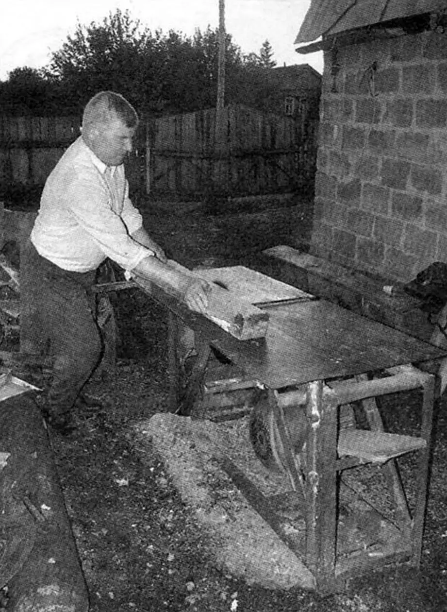
In a homestead-type house with a subsidiary farm and several auxiliary buildings, a wood-cutting machine, called a circular saw among craftsmen, is simply necessary for their maintenance and repair.
I have such a machine too, also homemade, like most of my “homestead” equipment. I made it with the calculation that it could perform carpentry and joinery work, saw firewood, and if necessary, cut metal by replacing the steel saw blade with a cutoff abrasive wheel.
The machine’s layout is, so to speak, classic. The drive, tables, and working parts are mounted on a common simple frame.
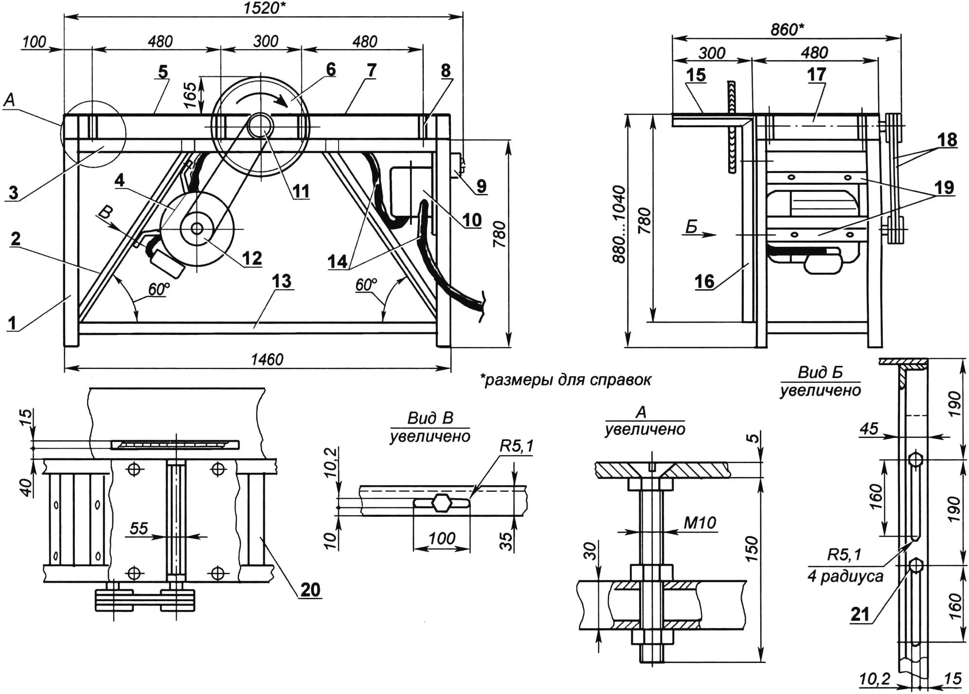
1 — frame post (angle 45×45, 4 pcs.); 2 — brace (angle 35×35, 4 pcs.); 3 — upper frame (tube 60×30); 4 — three-phase electric motor (N = 4.5 kW, n = 3000 rpm); 5 — receiving part of planing table (steel sheet s5); 6 — saw blade Ø450 (or cutoff abrasive wheel); 7 — feeding part of planing table (steel sheet s5); 8 — adjustable table support (bolt M10 with three nuts, 8 pcs.); 9 — push-button station; 10 — capacitor box; 11 — driven pulley; 12 — drive pulley; 13 — lower frame (tube 60×30); 14 — cables; 15 — lifting sawing table (steel sheet s5); 16 — sawing table subframe (angle 45×45, 2 pcs.); 17 — planer rotor; 18 — V-belts (profile B, 2 pcs.); 19 — slide (steel strip 455x50x10, 2 pcs.); 20 — upper crosspiece (tube 60×30, 2 pcs.); 21 — M10 bolt for lifting table subframe mounting (4 pcs.)
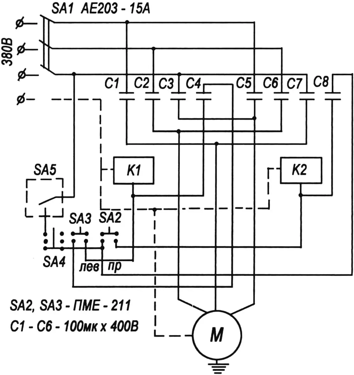
The machine drive is electric. The electric motor with a power of 4.5 kW and 3000 rpm is powered from a three-phase AC network with a voltage of 380 volts. On the frame, it is mounted so that the tension of the drive V-belts is achieved by its weight.
The frame is simple, welded. The posts are made of steel equal-leg angle 45×45 mm, braces — from angle 35×35 mm, and frames — both lower and upper — from rectangular tube 60×30 mm. Two connecting upper crosspieces are made from the same tube. The motor slides (two steel strips 455x50x10 mm) are attached to a pair of front braces with four M10 bolts. The braces also serve as guides when tensioning the drive belts: longitudinal slots are made in the braces instead of mounting holes.
Two L-shaped brackets made from the same angle as the posts are attached to the frame posts on the right side with M10 bolts. The upper parts (flanges) of the brackets serve as supports for the lifting part of the work table. A slot for the saw blade (or cutoff abrasive wheel) is cut in its plate.
Longitudinal slots are made in the bracket posts, which allow raising the posts (together with the sawing table plate) and covering the saw blade “overhang” above the table surface (approximately from 160 mm to practically 0).
The other two parts of the table — planing (feeding and receiving) — are mounted on the frame on adjustable supports. Long M10 bolts with countersunk heads and with nuts and locknuts are used as supports. The cutting (planing) depth of lumber is adjusted using the supports.
The main unit of the machine is the working shaft with a rotary planer and saw blade.
The shaft is mounted in two bearings N 80305. I used the bearings together with housings from abandoned collective-farm and state-farm agricultural machinery. I turned the shaft from steel 45, and the planer rotor — from duralumin. Later, I mounted the rotor on the shaft with a tight hot fit without keys and pins. I gave these parts to specialists for finishing: they ground the mounting surfaces on the shaft, and milled longitudinal slots for knives in the rotor.
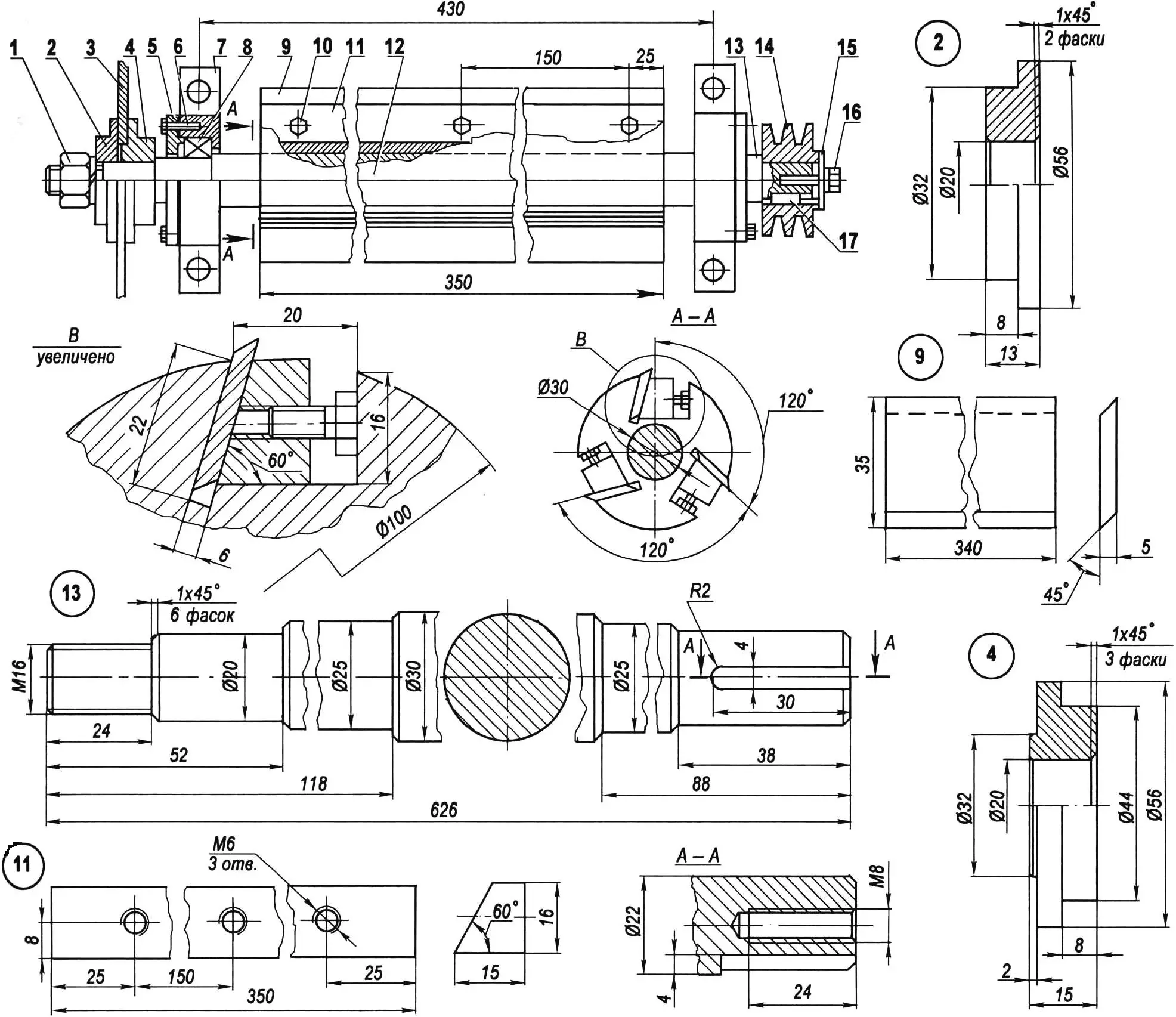
1 — M16 nut (tall) with spring washer; 2 — clamping flange (St3, round 80); 3 — circular saw (purchased item); 4 — mounting flange (St3, round 80); 5 — bearing housing cover (from agricultural machinery, 2 pcs.); 6 — M6 screw (8 pcs.); 7 — bearing housing (from agricultural machinery, 2 pcs.); 8 — bearing 205 (purchased item, 2 pcs.); 9 — knife (tool steel Р18, 3 pcs.); 10 — spacer screw M6 (9 pcs.); 11 — clamping bar (St3, 3 pcs.); 12 — rotor (duralumin, round 100); 13 — working shaft (steel 45, round 30); 14 — double-groove driven pulley (duralumin from metal-cutting machine); 15 — clamping washer (St3, round 52); 16 — M6 screw with spring washer; 17 — key (St3)
The planer rotor is three-knife. The knives — with double-edged blades, made of tool high-speed steel Р18. They are secured in the rotor slots with M6 screws by means of clamping bars.
Before assembling the working unit, specialists fitted the corresponding parts (knives, screws, and bars) by weight, and after assembly, they carefully balanced the unit: although the rotor diameter is small, the rotation speed is such that even a slight imbalance would cause significant vibration.
The double-groove pulleys of the drive’s V-belt transmission are duralumin with groove profiles for type B belts. I selected them ready-made from some dilapidated metal-cutting machine. The diameter of the driven pulley is slightly smaller than the drive pulley — therefore, the rotation of the planer rotor and saw blade is somewhat higher than the angular velocity of the electric motor, that is, slightly more than 3000 rpm.
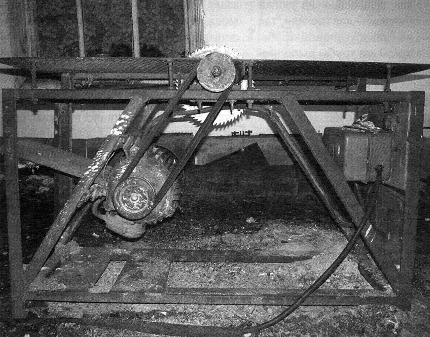
The circular saw is constantly in the yard on the homestead plot. Therefore, to prevent unauthorized activation by my grandson, in addition to the switch in the electrical panel and the push-button station on the frame, I equipped the machine with a “secret” — an additional, hidden from view, switch. I cover the working parts when the circular saw is not in use with a metal cover from above — an inverted old steel tub, attaching it at the corners to the table plates with small bolts.
I also provided for reverse (backward) rotation of the motor (and accordingly the working shaft) in the machine’s electrical circuit. This is not needed for the planer, but for the saw blade and abrasive cutoff wheel, such rotation is sometimes good — for convenience when working on the machine.
“Modelist-Konstruktor” No. 7’2006, V. KURAKIN
Recommend to read
 TO THE TRACTOR… ON THE TRACTOR
Mechanic Valery Kirilo from the village N. Chernychova the Brest region, built the Rover "KV-4" — jeep, which can work as a wheeled tractor. As a motor it has an engine "PD-10U".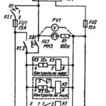 RELAY PROTECTION
Voltage instability in the regional power lines, unfortunately, are not so rare. Especially during strong winds, when the wires of overhead lines of 0.4 can overlap. Because of the...
