 Interest in homemade silencers due primarily to the poor quality of serial products. It is quite natural Amateur designer to improve their technique. Of course, significantly improve engine power due to the muffler at a given noise level of the exhaust gases is almost impossible, but to eliminate some of the shortcomings of industrial designs is still quite real.
First of all, you can do without perforated holes as the engine, is clogged with soot, causing the noise of the car increases slightly. In addition, the design of the main muffler, many domestic cars such that exhaust flow is forced twice to sharply turn 180°. This greatly increases the resistance and takes extra engine power.
Therefore, motorists may be interested in made by me muffler. To do the same is easy, and the metal content and mass — much less than factory. Applied as the primary muffler works in conjunction with the serial additional constructions (WHA) and in all modes of operation of the engine maintains about the same noise level not exceeding the permissible limits.
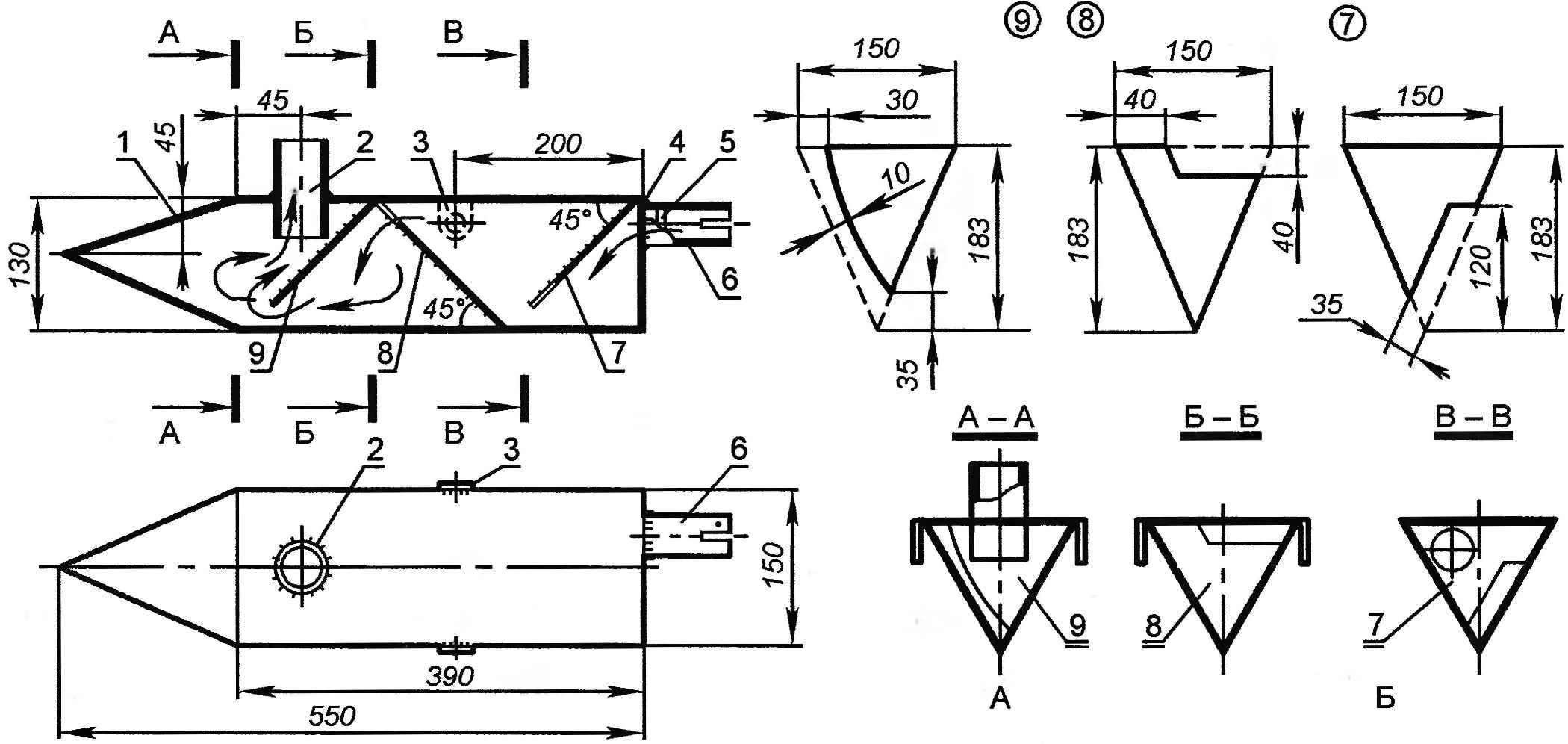
Fig. 1. Muffler:
1 — housing;
2 — the outlet;
3 — earring of attachment to the body (2);
4 —wall;
5 — the installation location of the flow divider;
6 — inlet nozzle;
7,8,9 —guiding plate.
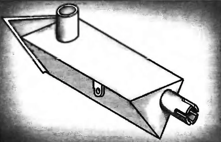
Exhaust silencer of an equilateral triangular prism, the front ending in a pyramid (Fig. 1). In the base of the prism welded inlet; at its end is made of four cutting — to ensure a secure fit of the exhaust pipe. The diameter of the latter are determined by all dimensions of the docking station.
Inside the muffler is placed at an angle of 45° relative to the longitudinal axis of the three guide plates. Between them and one of the faces of the body remains a gap, and the plate placed in such a way that each subsequent clearance covers the gap between the previous and the housing. Technologically it is possible to weld the plates only to the two faces of the housing, since the third overlaid and welded on the outside in the last turn.
