The term “gyro” comes from the Greek words autos — self, and gyros — rotation. They completely define the essence of this aircraft whose lift is created by air wines-Tom-rotor freely rotating under the action of the incoming air flow, and forward motion from the propeller-the propeller. The autogyro was invented by the Spanish aircraft designer Juan de La Ciervas in 1919; in 1923 he managed to create a device with good flight data.
In our country, the first autogyro was built in 1929 N. I. Kamov and N. To.Skrzynski. Until the beginning of the great Patriotic war was made about 15 of gyros of various modifications, one of these machines took part in the war as a scout and spotter.
Introduced in the late 30-ies of the helicopters quickly replaced gyros from a “large” aircraft. In our days, these aircraft were only in the Amateur and sporting aviation, where designers have created many of the most interesting machines of this type. In some countries, ultra-light single and double gyros are commercially available.
Geometry model of a gyroplane with the engine MK-17
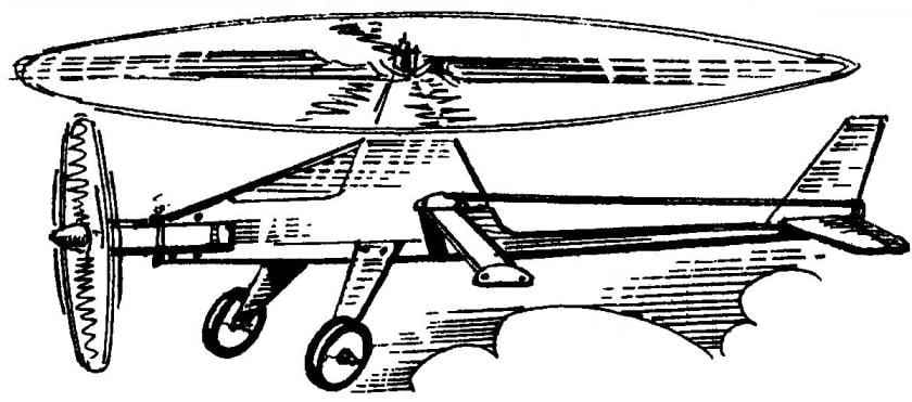
The layout of the gyrocopter:
1 — spinner; 2 —propeller; 3 —engine MK-17 “Junior”; 4—wheel chassis; 5 — landing gear (aluminum, sheet s2,5); 6 — mount the chassis (the bolt M3 with nut); 7 — mount crossmember (bolt with nut M3 and washer); 8 — fuselage skin (plywood s1); 9 — pull Elevator control (dural knitting needle d2); 10— skid (wire OVS d2); 11 — pylon rudder (aluminum s2); 12— keel (balsa plate s4); 13 — blade rotor-rotor (Linden, rail section 31×6); 14 — rear beam pylon (pine, raked a cross-section of 8×10); 15 — the main rotor hub-rotor; 16 — axis of the bushing; 17— an axis of the rotor-rotor (M3 stud with nut and washer); 18 — boss pole (Linden); 19— beam engine mounts (pine, raked a cross-section of 8×10); 20, the lower beam of the fuselage (pine, rail section 10×8); 21 — front of the fuselage beam (pine, raked a cross-section of 8×10); 22— Klondike (Linden); 23 — motor mount (M3 bolt with nut and washer); 24 — fuel tank (tinplate s0,3); 25 — crossmember (you-gluing five layers of plywood s1); 26— the ballast weight (lead weight of 30 g); 27 — the axis of the horizontal hinge main rotor blade (steel, wire d3); 28—horizontal tail (balsa, plate s4); 29 loop rudder (nylon, tape b10); 30 — the Elevator (balsa plate s4); 31 — a guide cord management (duralumin, sheet s1); 32 — the axis of rocking of management (M3 bolt with two nuts and two washers); 33 rocking control
However, back to the gyrocopter. It is a rotorcraft with two-bladed main rotor-rotor and power plant on the basis of the compression engine MK-17 a working volume of 1.5 cm3 .
The fuselage model is made up of pine slats and covered with 1 mm plywood. Two horizontal rails of the fuselage perform the function of the motor frame; the rear part of the bottom is a beam on which is attached the tail—fin and stabilizer with elevators. Perpendicular to the fuselage, along the axis of the screw rotor with two bolts and nuts fixed cross member, bonded with an epoxy resin of the five plywood pieces with a thickness of 1 mm — it is set rocking control, the ballast weight weighing about 30 g and the guide For cord management.
Tail zelenoborskoe. Keel, stabilizer and Elevator are cut from balsa plates with a thickness of 4 mm. Mount steering stabilizer — soft loops that represent segments of a nylon belt with a width of about 10 mm. Hog management — dural, on the wheel it is mounted using miniature self-tapping screws with a diameter of 2 mm.
Rotor-the rotor is two-bladed. Each of the blades is equipped with a horizontal hinge, not transmitting on the fuselage of the model the overturning moment arising. the blower blades (right the blade goes toward the oncoming flow, left flow; accordingly, a difference arises in lift forces on the right and left sides of the apparatus, and, accordingly, the moment of forces tending to overturn it). The blades are carved from Linden planks are, in fact, wings with a symmetrical profile relative thickness 20%; the maximum thickness of the blade is separated from her toe to a distance of 30 percent of the current chord.
The main rotor hub-rotor cut out and bent sheet of aluminum with a thickness of 2.5 mm. rod it is cut in accordance with scheme sweep with a small allowance; the final processing of parts and drilling of holes is carried out after bending of the workpiece. The joint sleeve consists of a cut aluminum tube with an inner diameter of about 4 mm and insertion of a segment of the writing refill gel ball pen. Mount insert is made with a metal mandrel, is heated to the softening temperature of the rod. Pitch adjustment of the rotor-the rotor is made by twisting the horizontal part of the hub — this can be done using two pliers. The hub axle is a steel pin with thread M3, plastered with lime in the pole top of the fuselage.
The blade rotor-rotor
The sleeve carrying the looking-rotor:
1 — body (duralumin, sheet s2,5); 2 — yoke (made of anodized aluminum, tube 5×0,5); 3 — insertion (tube rod gel pens)
Cross member:
1 — the base of the crossmember (you-gluing five layers of plywood s1); 2 — ballast weight (lead weight of 30 g); 3 — rivet (lead); 4 — cord management guide (duralumin, sheet s1); 5 — rail mount (rivet, aluminum wire d2)
Rocking control:
1 — rocking chair (made of anodized aluminum, the sheet s2,5); 2 — large bushing (part rod gel pens); 3 — small bushing (part rod ball-point pen)
Chassis model spring, it stands cut from a sheet of aluminum 2.5 mm thick and attached to the fuselage by a pair of bolts and nuts. Wheels with a diameter of 40 mm — plastic, from a suitable children’s toy.
The fuel tank model of soldered tinplate with a thickness of 0.3 mm. supply Pipe and also filling and drainage tubes of copper. Mount the tank to the fuselage with two screws-tapping screws.
The finish is just Vykurovanie and painting of suitable color topcoats.
The flight model are based on the cords length of 10-12 m. After warming up the engine it is recommended to turn the rotor and only after that send a model in flight. Unfortunately, lack of power polutorachasovogo MK-17 does not allow to make any complicated operations. After mastering takeoff, horizontal flight and landing makes sense to equip a model autogyro a more powerful engine — for example, type KDM-2.5 D.
I. SOROKIN
Recommend to read THE VALVE IS OF THE SPOOL Every modeller wants the motor on his model, and starts with one pull, and worked "like clockwork." But the fine-tuning motor is not only extremely high precision. It requires not only... CLOCKS FROM THE CLOCK Want to tell fans about his homemade clock designs-clocks. There is something very home 8 their peaceful ticking, measured swings of the pendulum. In our days, when the hours are not the...
 Cord model gyroplane with the engine MK-17. Readers of the magazine “modelist-Konstruktor” no need to explain, what is a gyro. However, the current model airplanes, most likely, have forgotten that such rotary-wing aircraft exists. But in the 60-ies of the last century among the approved classes, there was quite popular at korovikov class of models of the gyros, of the competition which was played at all levels up to the national championship. Today these rotary-wing aircraft create a few modelers. In this publication an attempt is made to awaken interest in this fascinating aircraft.