
The proposed development has, of course, nothing to do with space. In this case, PMC (Control Center) is a control center for only the power supply of electrical equipment, not for flights into the Universe. Constructively executed as a compact electrical panel, it contains the most essential automatic blocks for a garage. Here are the general distribution device, a thermostat for the cellar, a car battery charging point, a special module for connecting a three-phase motor to a 220 V household network, and a stabilized power supply. Moreover, all this is assembled from parts available even in the “hinterland”. The PMC works reliably and flawlessly.
The distribution device consists of a short-circuit and overload protection circuit breaker QF1 type АЕ1031М-2УХЛ4 with a trip current of 25 A, a pair of ordinary electrical outlets XS1—XS2, and two key switches brought out to the front panel. As for mounting and electrical cable routing, they are executed on a textolite or getinax board measuring 350x350x10 mm, installed inside the shield housing (case).
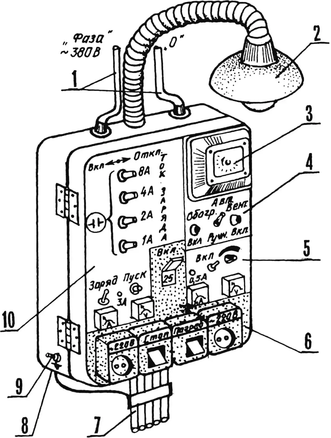
1 — input buses, insulated; 2 — flexible pendant luminaire (with position fixation in the work area); 3 — time relay (type 2 РВМ); 4 — thermostat panel; 5 — stabilized power supply panel; 6 — distribution device panel; 7 — output electrical cable (for load connection, 5 pcs.); 8 — protective housing, metal; 9 — PMC grounding; 10 — car battery charging point panel with three-phase motor connection module to household electrical network.
The thermostat for the cellar is more difficult to make — it’s electronics after all! It is designed to maintain the optimal, from specialists’ point of view, temperature (+4 °C), ensuring the best preservation of vegetables in winter. In summer, it serves to turn on ventilation and dry the cellar.
A mercury electrocontact thermometer is used as a temperature sensor, which is connected to the transistor VT1 bias circuit. The output stage is assembled on VT2.
In the initial state, when the temperature sensor contacts are open, both semiconductor triodes are closed. Voltage is applied through the normally closed contacts К1.1 of relay К1 to the heater. The latter starts working — and the temperature in the cellar rises. And when it reaches the set value, the thermometer contacts, closing, connect resistor R1 to the base of VT1 and open the input stage. That, in turn, opens transistor VT2.
Relay К1 operates. Opening contacts К1.1, it disconnects the heater from the network. But at the same time, it connects the air cooling fan with contacts К1.2. The temperature in the cellar decreases and reaches the point where the thermometer contacts open. Immediately both transistors operate, and the relay becomes de-energized. Connecting the heater to the network again with normally closed contacts К1.1, it opens К1.2 and disconnects the fan. To protect transistor VT2 from breakdown, the relay is shunted by diode VD1. It is this that suppresses the self-induction EMF arising in the winding when the output stage closes.
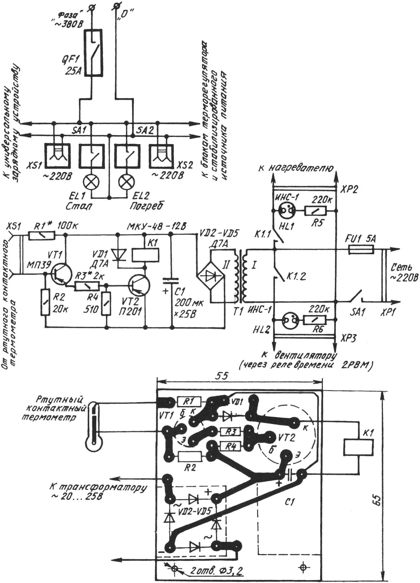
In the summer period, a heavy load falls on the fan — to ensure air exchange in the dried cellar. To ease such a stressful mode, the fan is connected to the network through a time relay type 2РВМ — a two-program, clock-type with a self-winding mechanism (it is conditionally not shown on the diagram). The first and second programs are designed to work for 24 hours, which allows easy setting of the periodic fan turn-on time. It is recommended, in particular, to program ten-minute breaks after every 20 minutes of its operation. The considered thermostat circuit can be successfully used to maintain the required thermal regime not only in the cellar, but also in other rooms. For example, in a garage, shed, chicken coop, incubator, greenhouse, and so on. Moreover, the set temperature depends only on the type of electrocontact thermometer used.
Now about the parts. As VT1, МП25, МП26, МП39—МП42 with any letter index will do; VT2 — П201 — П203, П213—П217; the relay should be rated for 12 V and have contacts that can withstand a load of up to 1 kW. Transformer — ТВК-110ЛМ-К or any other with voltage on the secondary winding from 14 to 20 A and power of 10—20 W.
When starting adjustment, the XS1 connector sockets are temporarily connected with a wire jumper. If the relay “does not respond”, then the emitter and collector leads of VT1 are shorted, and by selecting R3, reliable operation of К1 is achieved.
After removing both jumpers, the relay should “release”, and when the XS1 connector sockets are closed again, it should operate again. Otherwise, R1 is selected with the required rating or VT1 is replaced with another one with a higher static current transfer coefficient.
The stabilized power supply will allow doing without batteries when operating a radio receiver, audio recorder, electronic clock, electronic games. It is assembled on the КР142ЕН2Б integrated circuit. It has protection against short circuits in the load and allows adjusting the output voltage from 2 to 24 V at a current of 0.5 A. If КР142ЕН1Б is used instead of КР142ЕН2Б, the adjustable voltage will be only 2—12 V.
As for other circuit elements, it should be noted that transformer Т1 here, as before, is ТВК-110ЛМ-К or similar. The transistor КТ603 indicated on the circuit can be replaced with КТ630, it will work no worse. As for VT2, it is better to use КТ803А. Moreover, it requires a heat-dissipating radiator with a cooling area of 30 cm2. Mounting — printed, on 2-mm foil-clad textolite or getinax.
The car battery charging point is also executed by the printed method according to a well-proven circuit in practice. The board is made of 1.5—2-mm foil-clad textolite (getinax). A correctly assembled unit usually starts working immediately and provides charging of 12-volt battery packs with a current of up to 15 A. Moreover, the charge current can be changed in steps of 1 A.
Automatic shutdown is provided when the battery is fully charged. It should be noted that the circuit is not afraid of short-term short circuits in the load circuit and breaks in it. And the capacitor assembly at the input allows using the elements included in it (with the charger disconnected) to connect a three-phase half-kilowatt motor to the household network (220 V, 50 Hz).
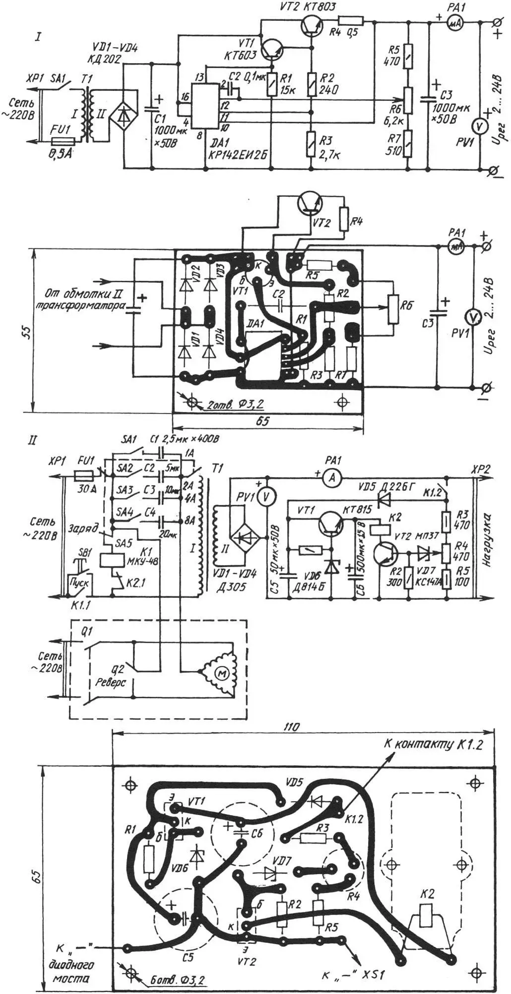
I — stabilized power supply; II — car battery charging point.
The capacitor bank consists of four capacitors with a total capacity of 37.5 µF. With switches SA1—SA4, various combinations of electrical capacities can be easily created, thereby changing the charge current setting. For example, to obtain 11 A, it is only necessary to close toggles SA1, SA2, and SA4.
It makes sense to consider the operation of the proposed circuit in more detail. Suppose that a battery pack is at output ХР2, and the required charge current is set with switches SA1 — SA4. In this case, when pressing SB1 “Start”, relay К1 will operate. With contacts К1.1, it will lock button SB1, and with К1.2, it will connect the automatic device shutdown circuit to the battery. The last pair of contacts is necessary to exclude the possibility of battery discharge (after disconnecting the circuit from the network) through diode VD5 and resistors R3—R5. Potentiometer R4 is needed to set the operating threshold of relay R2 (at voltage at output ХР2 equal to the voltage of a fully charged battery).
When the voltage at the battery terminals reaches 14.5—15.2 V, zener diode VD7 and transistor VT2 will open. Immediately relay К2 will operate and disconnect the charging point from the network.
A similar result will occur when the contact in the load circuit is broken. After all, the voltage at ХР2 in this case should rise sharply. Relay К2 will operate and disconnect the entire circuit from the network. Moreover, emergency shutdown will occur at any position of the variable resistor R4 slider.
The parts here are the most common. As VT1, for example, КТ801А, КТ602, КТ603, П701 will work well. And in place of VT2, МП37, КТ315, КТ312, КТ601-КТ603 will work well. Relay К1 is desirable to take type МКУ-48, rated for 220 V, and К2 — type РЭС-15 or any other for 12 V. Diodes Д247, Д246, and Д305 are placed on a radiator with a total cooling area of 300 cm2.
Capacitances С1—С4 are composed of parallel-connected capacitors type КБГ-МН, МБГЧ (МБГО, МБГП). Moreover, the operating voltage of КБГ-МН and МБГЧ, designed for operation in alternating current circuits, must be at least 400 V. And for all other types — at least 600 V. Capacitors С5—С7 — К50-3, К50-6, ЭГЦ.
Transformer Т1 is made on a Ш32х100 magnetic core. Winding I — 320 turns of ПЭВ-2 with a diameter of 1.16 mm, II — 34 turns of ПЭВ-2 with a diameter of 2.46 mm.
In the three-phase electric motor connection module, the capacitor bank installed in the charger is used. To involve it in work in a new capacity, it is necessary to set the package switch SA5, as well as toggles SA1—SA4 to the position marked on the panel with the corresponding sign. Contact Q2 then serves to change the direction of rotation of the electric motor, and Q1 — to connect the latter to the 220 V network. Instead of the “package” SA5, a homemade device assembled from three МП type microswitches, which are actuated simultaneously by one handle, can be used. If it is required to turn on the charger, then SA5 is set to the “Charge” position (as in the diagram), and SA1 — SA4 — to any set charge current.
«Modelist-Konstruktor» No. 10’2000, A. NARVATOV, engineer
Recommend to read
 “FISHING” WITHOUT WATER
The kids, happily folding cubes and collecting of the pyramid, and did not suspect that this so-called educational games designed to develop quickness and coordination. But they have... CLAMP AND VISE
There just clips and the clips do not come up with designers - and all this only in order to securely attach bench vise on the workbench. Not everyone, however, can be used in a home...
