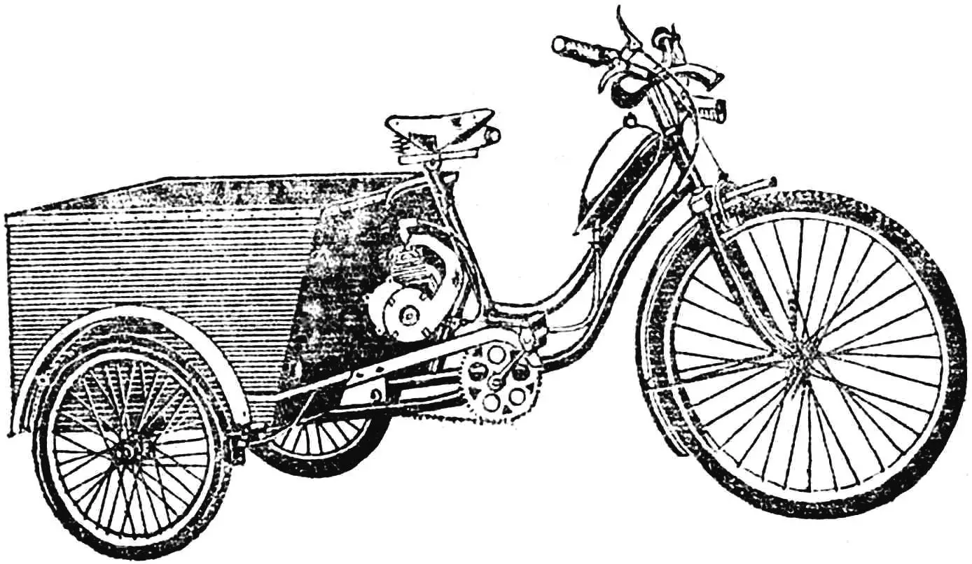
This three-wheeled motorized cart was created for garden and household purposes; it is convenient for transporting bags, tools, and other small loads. The engine here is a conventional bicycle motor D-6, quite widely used in garden and vegetable garden associations for driving tillers, cultivators, pumps, and mowers. However, its design is intended for cooling from the oncoming airflow during movement.
For operation in unusual new conditions, it is necessary to equip the bicycle motor with a forced cooling system, which I did when making my motorized cart.
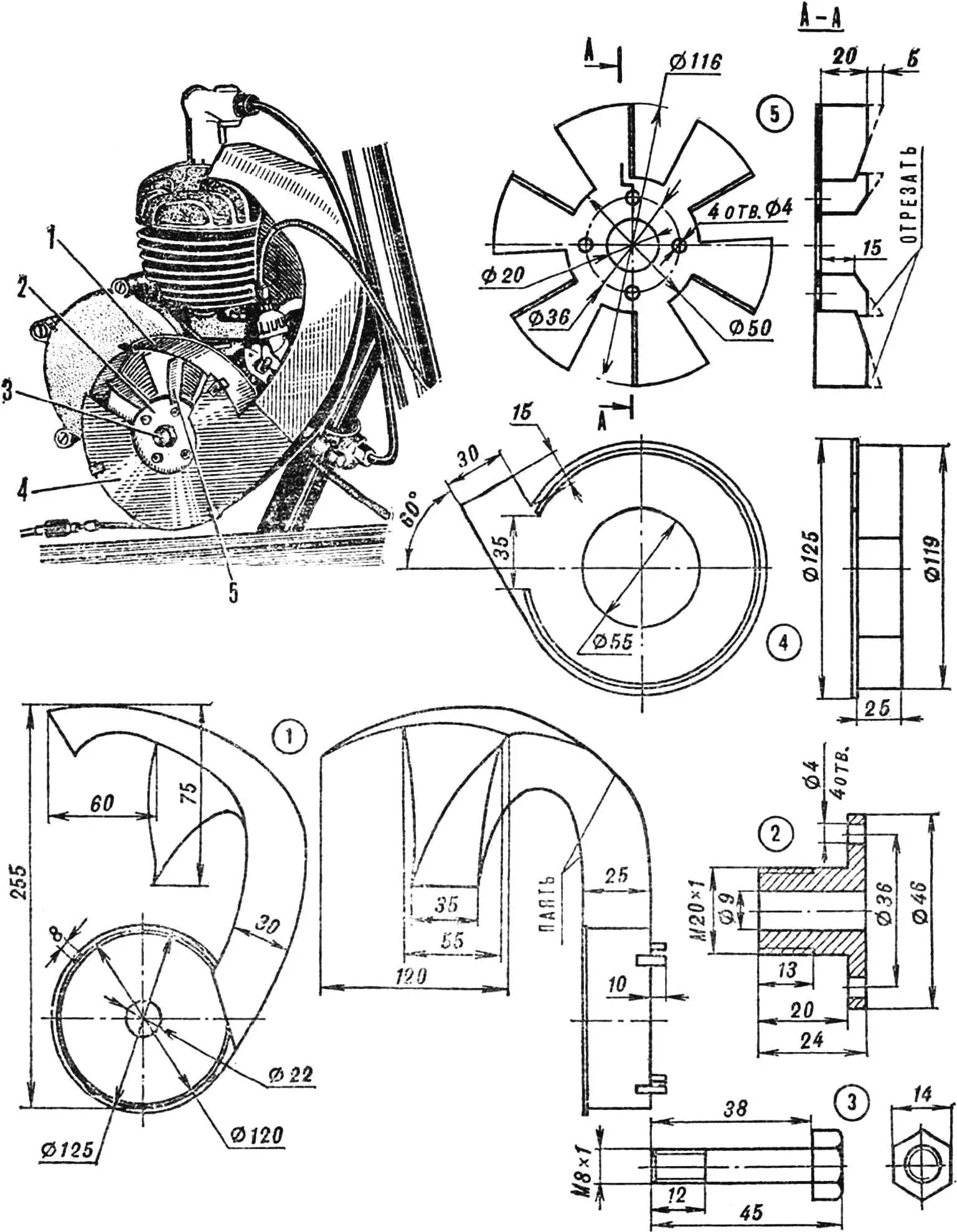
1 — housing, 2 — bushing, 3 — M8 bolt, 4 — housing cover, 5 — impeller.
I based it on a design published in the article “Bicycle engine on a motor cultivator” (“M-K” No. 8, 1979), but slightly modified it, adapting it to my machine. The engine improvement consists of installing a centrifugal fan enclosed in a housing on one of the crankshaft tail ends. It directs the airflow to the most heated parts: the cylinder head and the upper part of the cylinder.
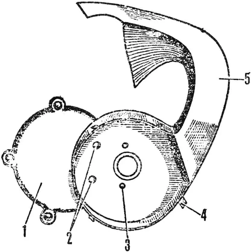
1 — clutch cover, 2 — rivets, 3 — bolt hole, 4 — retainers — tin strips, 5 — housing with air duct.
In the engine itself, only the clutch cover needs to be modified. First, bore a through hole Ø 29 mm in its wall, coaxial with the driving gear seat of the crankshaft. Then, from a duralumin sheet 0.5—1.0 mm thick, cut out the fan impeller. I recommend bringing the height of its six blades to 20 mm. It is attached to the crankshaft using a bushing and an M8 bolt, which are easy to turn on a lathe. The housing and air duct blanks are cut from sheet galvanized tin and soldered into a rigid box with an internal channel directing the tangential airflow from the impeller to the cylinder head from the front (and not from the side, as recommended in the article). This layout does not require repositioning the head. In addition, the air duct, having a small thickness, does not interfere with normal cooling by the oncoming flow. The housing is attached to the clutch cover with a pair of aluminum rivets, as well as two of the five bolts that secure the cover to the engine crankcase. The housing cover with a central air intake hole is also soldered from tin. With its high rim, it fits tightly inside the housing and is fixed in this position by four tin strips soldered on the outside.
P. STANEVSKY, Kyiv
Recommend to read
 THE SECOND LIFE OF AEROSOLS
Cylinders from under the aerosol can be used repeatedly, if you apply a small improvement. This requires only valve from the tire of a racing bike... and a little ingenuity. THE... MINI CAR FOR KIDS
The first little micro-car "mouse" I built for my kids. As far as he was able, the readers of "Modeller-designer" can tell, after reading his description and drawings, published in...
