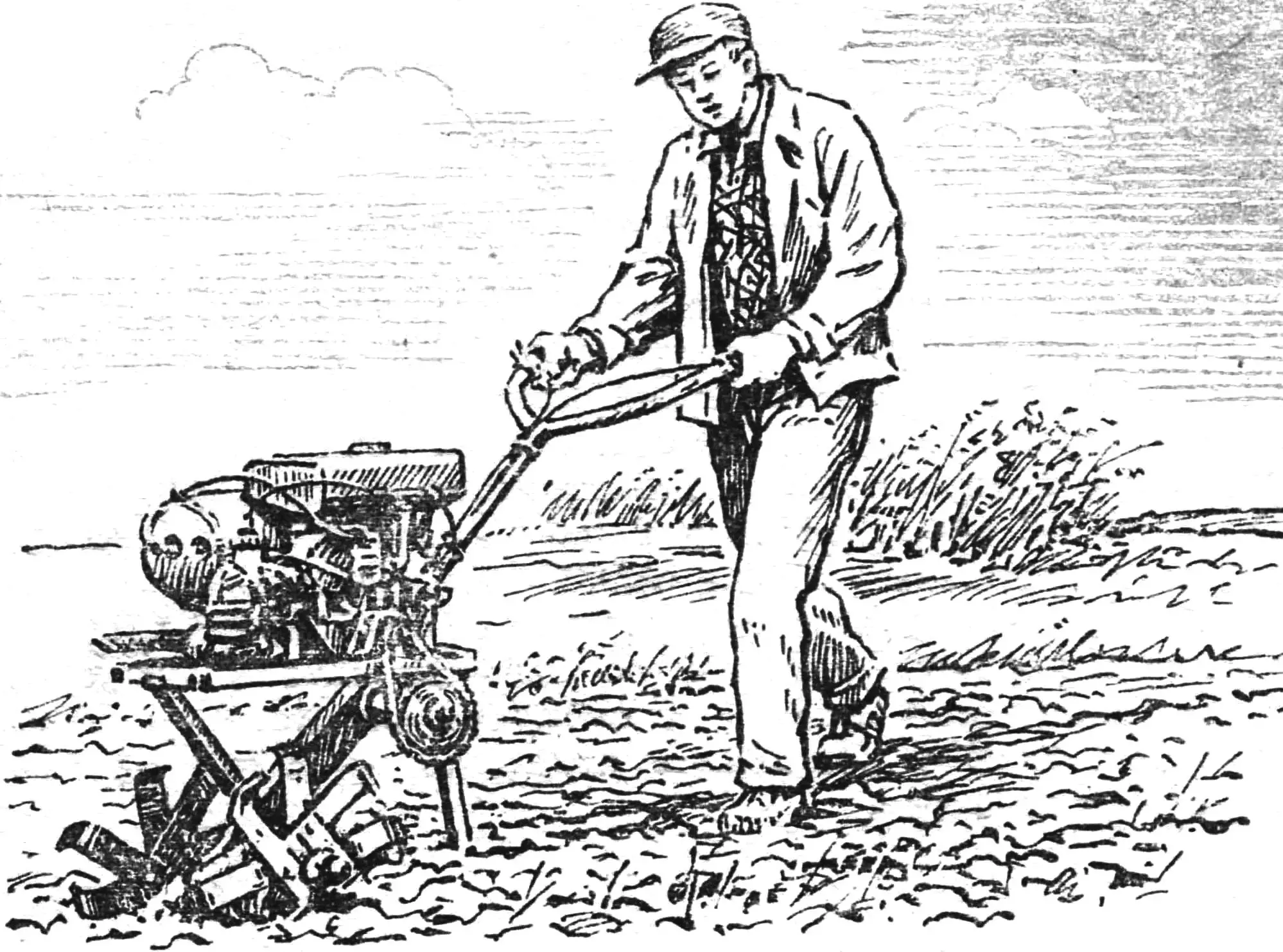
The tiller developed by Heinrich Alekseevich Kuznetsov differs from many homemade designs by using cutters instead of a plow. Rotating on the working shaft, they simultaneously till the soil, serve as support elements and propulsion. It takes only a few minutes to replace them with wheels. Then it’s easy to attach a disc mower, bulldozer blade, plow, hiller, harrow, or a two-wheeled dump cart with a capacity of 300 kg, equipped with brakes, to the tiller. With the help of a special device, you can process strawberry beds and transport logs.
The weight of the tiller with a full fuel tank is 72 kg (for comparison: MTZ-05 weighs 135 kg), there are three gears, the speed is 4—25 km/h. One hundred square meters can be plowed with this machine in 12—15 minutes at a processing depth of up to 230 mm.
The tiller uses an engine from the “Vyatka” scooter, which has air cooling, and forced at that, which allows it to work for a long time under maximum loads. Minor modifications relate to the clutch lever, carburetor, engine starting system, and gearbox. So, for ease of control, the clutch lever is rotated 180°: a pin is cut off from its rod at the very base, moved to the other side of the rod and welded there. This made it possible to place the clutch handle under the left hand and reduce the length of the transmission cable.
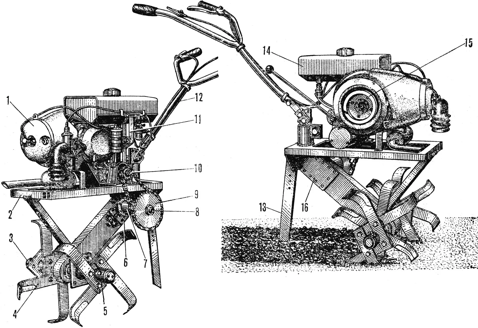

1 — engine, 2 — tiller frame, 3 — working shaft, 4 — cutter blade, 5 — cutter hub, 6 — adjustment plate, 7 — intermediate shaft bearing housing, 8 — intermediate shaft, 9 — sprocket, 10— power take-off shaft, 11 — fuel tank bracket with clamp, 12 — handlebar, 13 — support leg, 14 — fuel tank, 15 — starter pulley, 16 — cover.
On the left view, two cutters are conventionally not shown.
The carburetor nozzle connecting it to the engine is rotated so that the carburetor is as low as possible relative to the fuel tank: after all, fuel flows to it by gravity. The kickstarter lever is removed. Starting is done using a nylon cord wound on a homemade starter duralumin pulley Ø120 mm. It is installed in a housing on the fan axis next to the latter. To secure the cord, a knot at its end is inserted into an inclined groove on the pulley rim. A control lever more than 400 mm long is welded to the gear sector located in the gearbox, which allows shifting speeds while being directly behind the handlebar handles. When installing the sector in place (on the axis) after welding, pay attention to the fact that the lever should initially be in the neutral position.
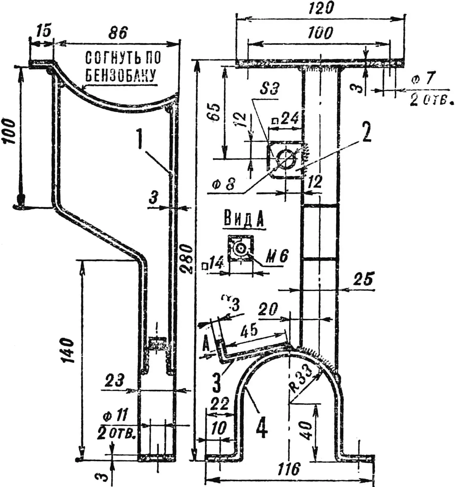
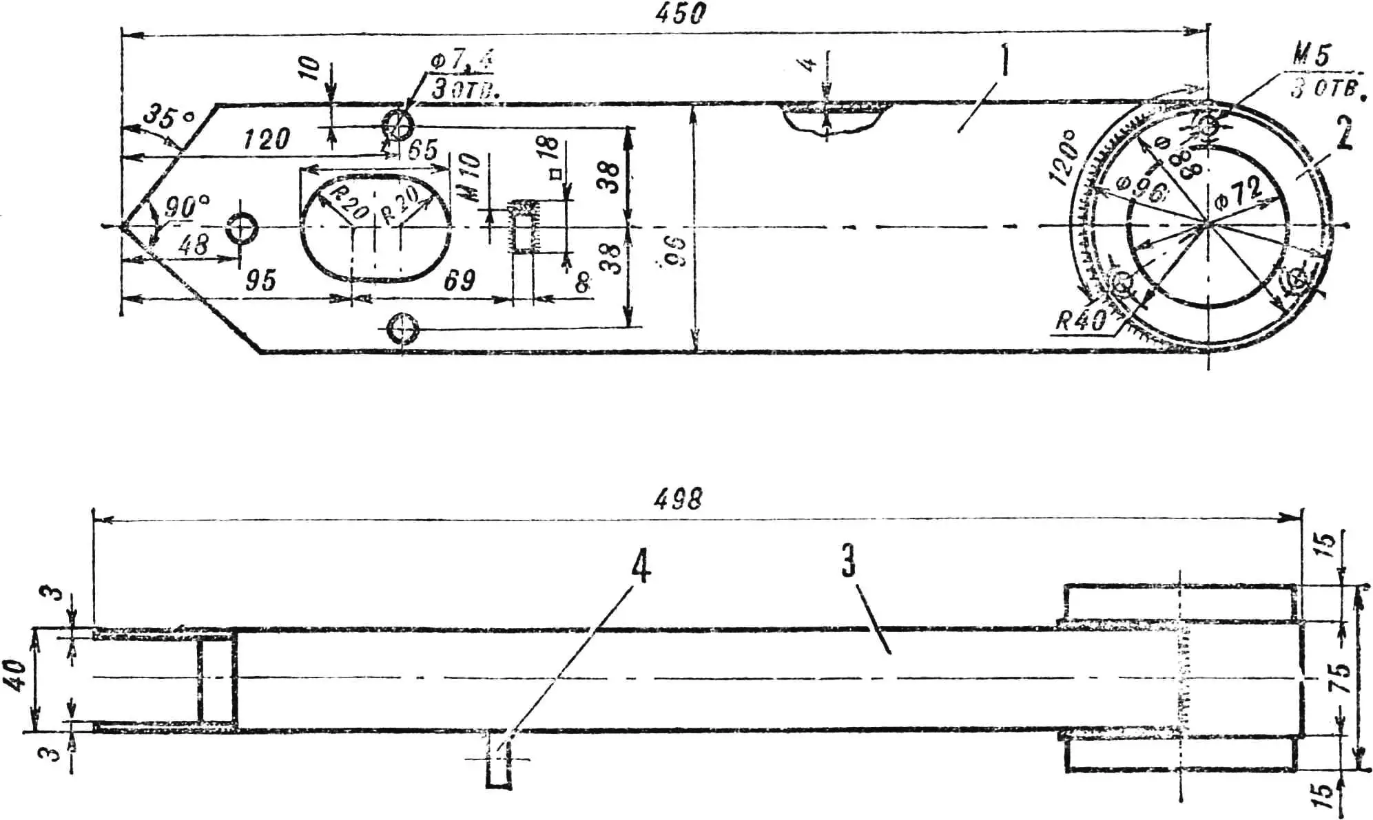
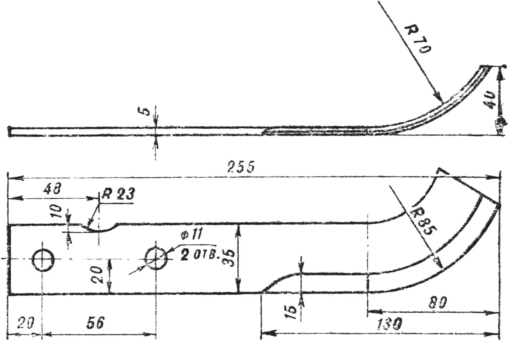
The tiller frame is welded and is a quadrangle (600×210 mm) made of rectangular box profiles 27X25X2 mm; the rear part is closed with an angle. A transmission box with a main shaft housing extends downward from it, supported by a stop. A motor bracket is welded to the top of the frame, and a power take-off shaft housing clamp together with a fuel tank bracket is mounted on bolts. The clamp is made from a steel plate 23 mm wide and 3 mm thick; holes for M10 bolts are drilled at its ends. The engine bracket is made of two steel strips 32×4 mm. One is bent into a U-shaped profile: in its center there is a 23X10 mm cutout for the engine bolt; the other — reinforcing — is welded to it at the top from the inside.

1 — frame, 2 — engine bracket, 3 — handlebar turn and lift unit housing, 4 — hitch pad, 5 — transmission box with working shaft housing, 6 — frame angle, 7 — box stop.
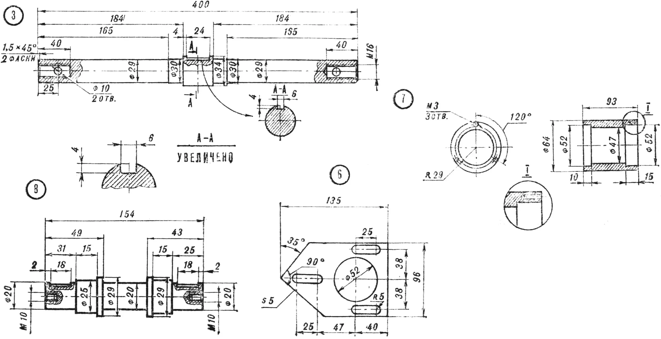
The transmission box is welded. Its base is made of metal strips 40X4 mm, the cheeks are of a somewhat more complex configuration with holes and cutouts. With its upper end, it is welded to the frame angle, extending from it at an angle of 35°. Therefore, the cheeks are cut here differently: on one edge at an angle of 35°, on the other — at an angle of 55°. A sector with a radius of 48 mm for the main shaft housing is cut out at the lower end of the box. In the right cheek (when looking at the tiller from the front), three holes for M6 bolts are drilled to fasten the secondary shaft adjustment plate (during assembly). In connection with the need to adjust the position of the secondary shaft and chain tension during assembly and operation, an elliptical hole for the shaft is provided.
1 — bracket, 2 — switch mounting eye, 3 — cable mounting bracket, 4 — clamp.
In addition, a square M10 nut is welded here: an adjustment bolt of the plate with a locknut is screwed into it. The left cheek, unlike the right one, has a larger elliptical hole. This is necessary for putting the chain on the sprockets, tightening the plate bolts from inside the box and ensuring the possibility of lubrication and inspection of the units. The hole is closed with a cover on ten M5 bolts. In short, the box is a subframe part of the structure, on which the main transmission parts are mounted.
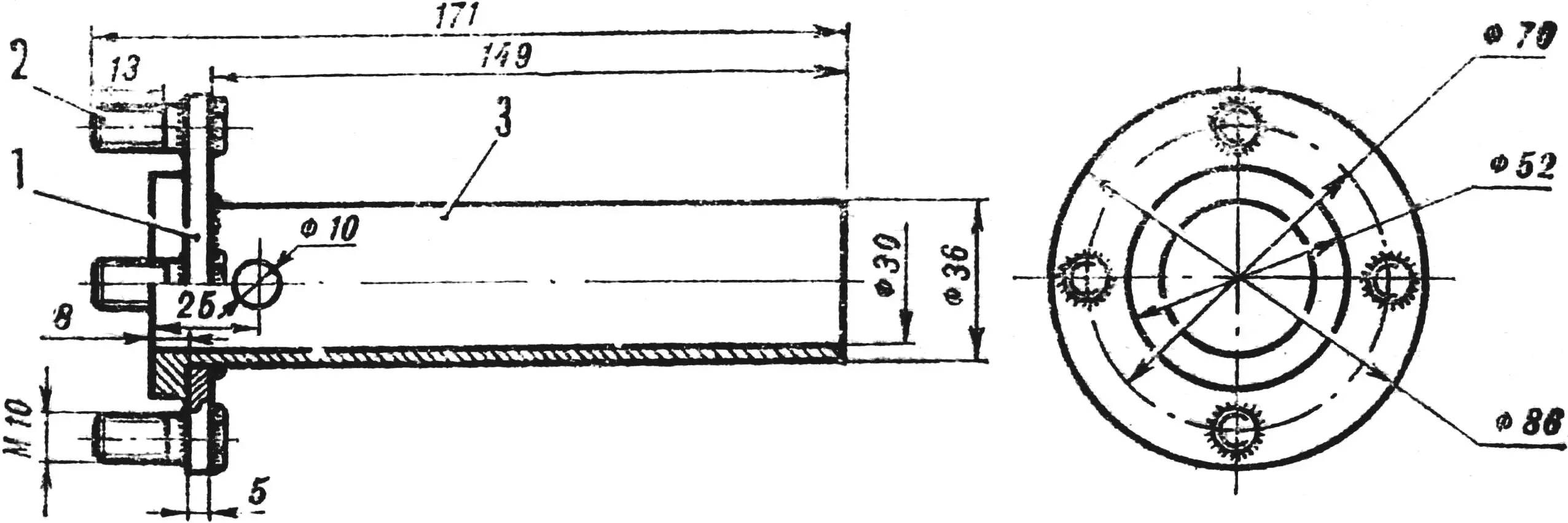
The transmission of forces from the engine to the working organ of the tiller occurs as follows. A sprocket with the number of teeth = 11 is installed on the power take-off shaft. The intermediate shaft has two sprockets with Z=41 and with Z=11: the latter is brought into the box and is the driving one relative to the working shaft, on which there is another one with Z=15. The chains — there are two of them — are taken with a pitch of 12.7 mm.
1 — right cheek, 2 — housing, 3 — “strip”, 4 — intermediate shaft plate adjustment nut.
With the help of the intermediate shaft, the force transmitted to it is “moved” to the central plane of the unit, as well as reducing the number of revolutions. The shaft itself rotates in two bearings pressed into a metal housing, which in turn is welded to the adjustment plate. Having three special holes for mounting bolts on the box, the plate can move along it, adjusting the chain tension: it is fixed by a bolt of the adjustment nut on the cheek. The inner bearing is installed in the housing so that it partially enters the central hole of the plate.
A few words about the assembly order of this unit. First, the outer bearing is pressed into the housing and the shaft is inserted. Then the inner bearing is put in place and the plate is put on its remaining free part. Carefully, with breaks so as not to overheat the unit parts, it is welded to the housing and secured with bolts on the box. Finally, the box is welded to the frame with the upper ends of the cheeks. Pay attention to the fact that between the frame and the power take-off shaft sprocket with Z=41 it is necessary to leave a gap of 15 mm for free chain travel.

1 — power take-off shaft sprocket (Z = 11, Ø = 50 mm), 2 — intermediate shaft sprocket (Z = 41, Ø = 171 mm), 3 — intermediate shaft sprocket (Z = 11, Ø = 50 mm), 4 — working shaft sprocket (Z = 15, Ø = 66 mm).
The main shaft unit is assembled in approximately the same way, that is, they start by pressing the bearing into the housing, insert the shaft, fix the sprocket on the key and install the second bearing. After the housing is closed with covers, they proceed to weld it with the cheeks, and then, having carefully checked them for parallelism, weld the box strips to them. This order of assembly operations must be observed so that the metal of individual parts does not warp during welding and their displacement relative to each other does not occur.
A few words about the running gear and working organs. As already mentioned, replacing cutters with wheels is a matter of minutes, you just need to remove the cutter hubs and put on hubs with wheels. Each of them consists of a bushing, a flange and four pins: their connection to each other is welded. The pins have threads for nuts to secure wheel discs on them. In addition, holes Ø10 mm are drilled in the bushings — the same ones are on the ends of the working shaft: when hubs with wheels are put on the shaft, these holes are aligned and a cotter pin is inserted into them.
1 — flange, 2 — bolt M10X25, 3 — bushing.
The cutter hub has two flanges on the bushing: outer and inner; one relative to the other is rotated 45°. The blades are installed on both sides of the flanges in pairs, parallel to each other, with the “point” in different directions; they are fastened with M10 bolts. A total of 16 cutters made of 5 mm thick metal strips rotate on the working shaft. The cutter hubs are also put on the working shaft and secured with cotter pins.
It is better to assemble the tiller following this order. The frame with welded units and parts is installed on wheels and fixed in a horizontal position using a support leg. The engine is placed on top so that the power take-off shaft sprocket and the intermediate shaft sprocket are in the same vertical plane and the transmission chain could freely pass between them and the frame. Therefore, the groove in the bracket for the engine mounting stud is cut only after such a “fitting”. Then the bracket with the clamp is installed (in place), both chains are put on and their tension is adjusted. A housing is placed on the primary transmission (the box covers are carefully closed so that earth and dust do not get into the transmission), the fuel tank and ignition system devices are connected.
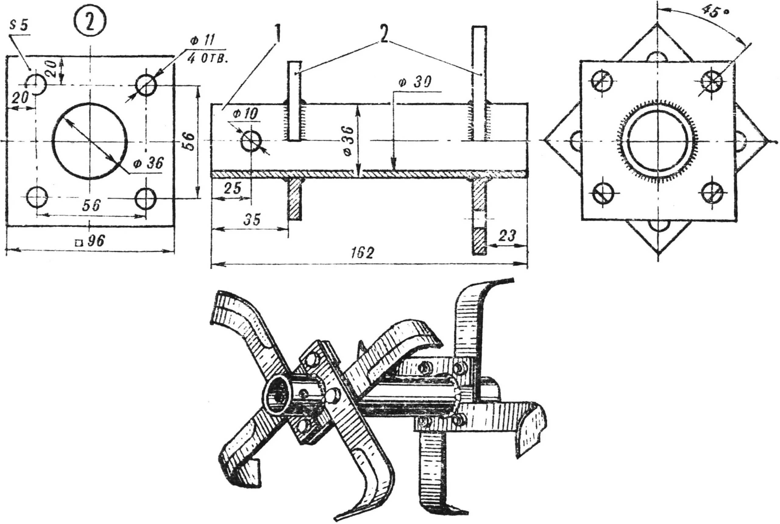
1 — bushing, 2 — flanges.
If when working on wet soil, on viscous soil, the tiller with wheels will slip, make circular lugs that can be put on the wheels if necessary. For this, two rings are welded from wire Ø8—10 and 1287 mm long (for “Vyatka” scooter wheels). Twelve arcs of lugs made in the form of segments from a metal strip (15—20 mm wide and 3—5 mm thick) with an internal radius of 120 mm are welded between them, and also — in any place of the ring — a tie from an M8 bolt with a nut is installed. By cutting off a small piece of wire under the tie, we get the ability to adjust the tension of the lug rings to remove or, conversely, secure them on the wheel.
«M-K» 10’83, G. KUZNETSOV
Recommend to read
 FIRST AIRCRAFT MODEL
These beautiful and flying planes are very simple. Even preschoolers can make them with the help of adults. To work, you will need thick paper (whatman paper), several dry and straight... OUR ANSWER “STRATOJET”
Long-range bomber Tu-16. Large-scale development of high-speed jet bombers, long-range flight, which began in the USA after the Second world war, could not remain unnoticed in the Soviet...
