For more than ten years I have been designing and building all-terrain vehicles. Over these years I have gained some experience, but I constantly turn to new publications in “Modelist-Konstruktor”: what if someone, having come up with something original, did better?
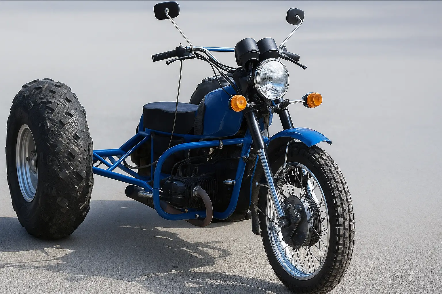
The prototype of the proposed tricycle was a machine I made based on an “Izh” motorcycle with two drive chamber wheels and a steering ski. It seemed the desired result was achieved: the machine ran quite well on snowy off-road terrain. However, the ski on packed snow did not cope well with the task assigned to it. Spring revealed other shortcomings of this design. Riding on roads with patches of bare ground disabled even a stainless steel ski. Instead, I installed a pneumatic tire from a 12.00—18″ inner tube, but now the lack of a differential made itself felt to a greater extent — the snowmobile was very difficult to control.
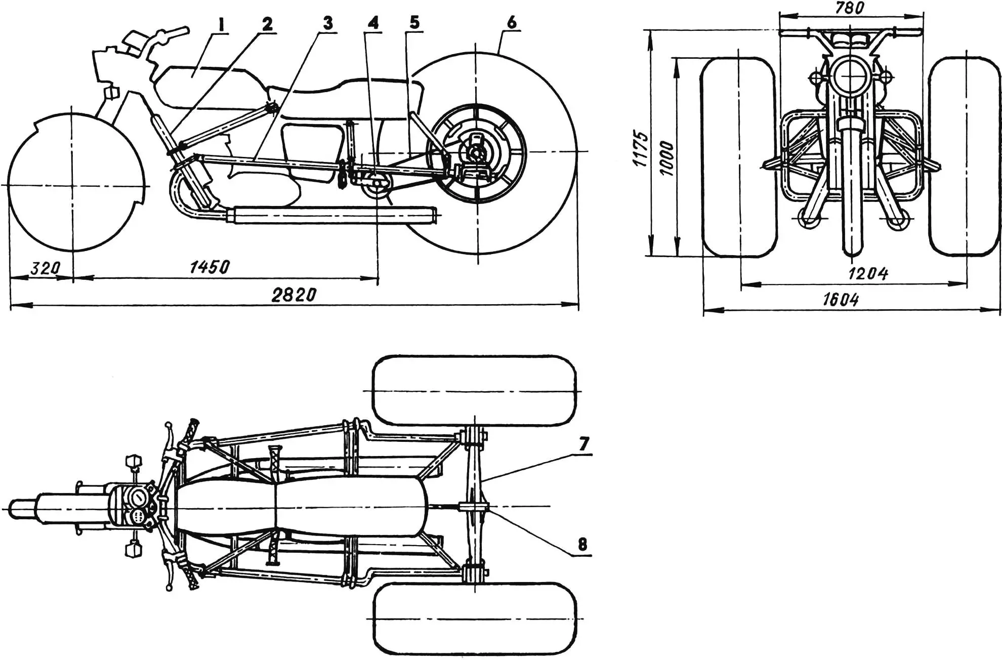
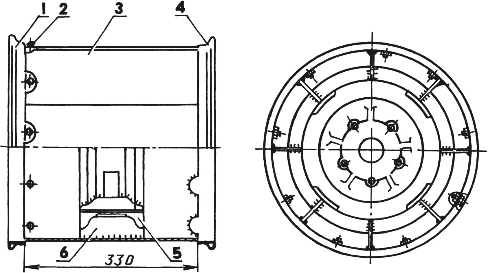
1 — “Izh-Jupiter” motorcycle; 2 — left safety arch; 3 — additional frame; 4 — drive sprocket with hub (z = 18, from “Izh-56” motorcycle wheel); 5 — drive chain (t = 19.05); 6 — pneumatic tire (modified tire from GAZ-66 vehicle); 7 — rear axle (from “Moskvich-402” vehicle); 8 — driven sprocket housing.
On the side view, the left wheel with hub is conventionally not shown
Then I built a reducer from an old GAZ-51 truck into the rear axle. The machine became maneuverable, but other problems remained, and the main one — chamber pneumatics, they barely lasted a year. I racked my brains for a long time about what to replace them with, and somehow I was told about the technology of mechanical rubber cutting, which turned out to be very useful. I decided to make tires for the pneumatic vehicle by cutting off part of the tread from truck tires, and at the same time radically improve the entire design.
It took me almost the entire winter just to make the rear axle and wheels. So if anyone decides to follow my example, let them be patient. But as a result, they will get a machine that will serve them for many years. With such wheels, the speed increases sharply, since there is practically no vibration, and cross-country ability improves significantly — the presence of lugs makes itself felt.
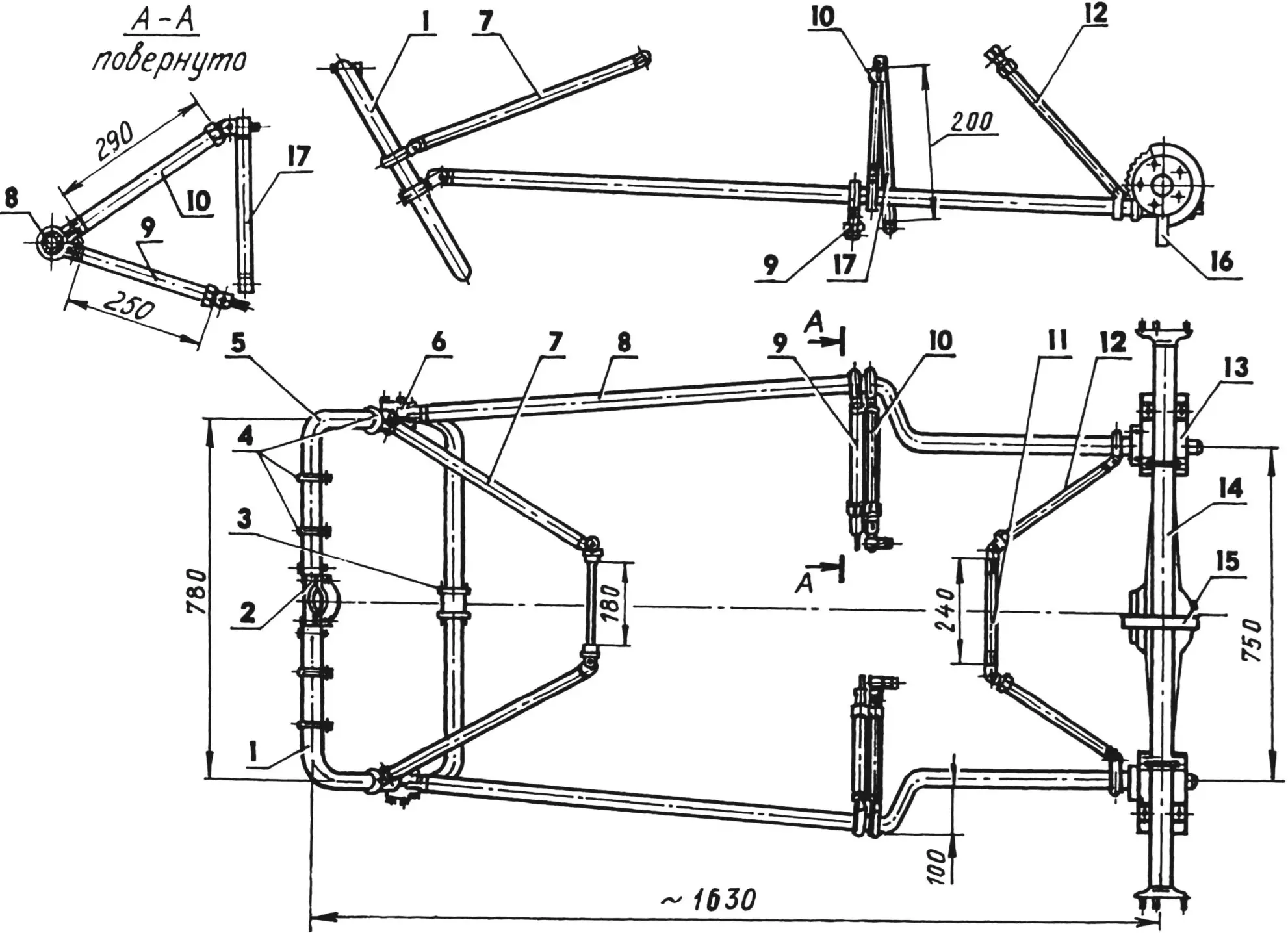
1,5 — safety arches (chrome-plated steel tube 34×3); 2 — detachable bracket (St3); 3 — cheek with boss (St3, sheet s8, 2 pcs.); 4 — clamps (St3, 12 pcs.); 6 — detachable bracket (steel, sheet s15, 2 pcs.); 7 — brace (chrome-plated steel tube 27×2.5, L505, 2 pcs.); 8 — side member (stainless steel, tube 34×4, L1400, 2 pcs.); 9 — passenger footrest rod (chrome-plated steel tube 27×2.5, 2 pcs.); 10 — shock absorber rod (chrome-plated steel tube 27×2.5, 2 pcs.); 11 — spacer (steel, tube 27×2.5); 12 — seat rod (chrome-plated steel tube 27×2.5, L320, 2 pcs.); 13 — docking unit; 14 — rear axle; 15 — driven sprocket housing (steel, sheet s2); 16 — bow truss (steel, sheet s8); 17 — shock absorber strut (chrome-plated steel tube 27×2.5, 2 pcs.)
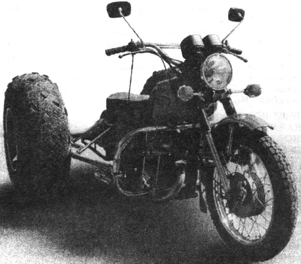
As far as I understood, among design enthusiasts who saw my all-terrain vehicle, what aroused interest was not so much the vehicle itself — its design is not that complicated — but the original wheels with tires. Therefore, I provide a fairly detailed description of their manufacture.
For the pneumatics, I settled on tires sized 12.00—18″, such are mounted on wheels of GAZ-66 and ZiL-157 vehicles. For a snow-swamp vehicle, tires from wheels of K-700 and T-150 tractor carts are also acceptable. They are significantly wider, but unfortunately, also heavier. I chose the 18″ tire mounting diameter because I could make a wheel from parts I had. If someone has the opportunity to purchase 12.00—16″ wheels, I would consider them lucky.
Even tires that are not suitable for welding will work, but without through punctures. Many hunters used to have to cut wads for rifle cartridges from felt themselves. Well, a cutter similar to a wad cutter became my main tool for a long time. To insert the cutter directly into the drill instead of a chuck, I made it with a corresponding taper (working with a wad cutter clamped in a drill chuck, you get tired faster). I took arbitrary dimensions for the cutter, and sharpened it simply: turned on the grinding wheel and brought the cutter rotating in the drill to it.
The number of “Christmas trees” on the wheel tread is such that it did not allow “thinning” them by skipping one without disturbing the balance. Therefore, marking them with chalk, I did this: cut one — leave one, cut two — leave one, and so on in the same sequence. And in the “Christmas trees” I arranged the lug bosses at my discretion. Before milling, I inserted a tube into the tire and inflated it. This way the layer between the tread and cord was better felt, although I still sometimes caught cord threads, but the carcass is multi-layered and these flaws did not affect the tire strength. (There is another, simpler technology: they simply strip the rubber from the tire down to the cord, but then they lose the most valuable — powerful lugs on the tire.)
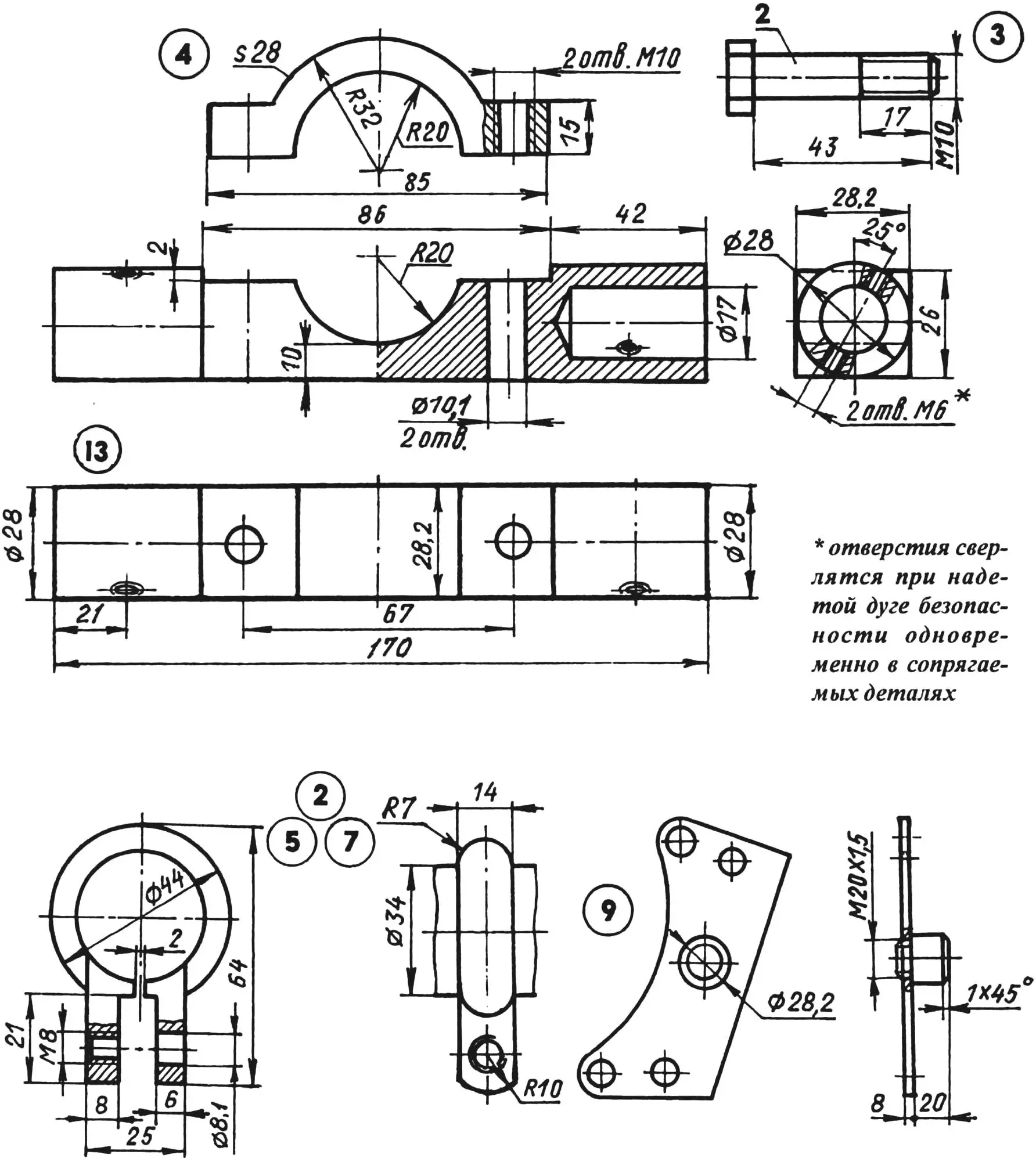
1,6 — safety arches; 2 — fog light mounting clamp (2 pcs.); 3 — M10 screw (2 pcs.); 4 — detachable bracket; 5 — horn mounting clamp (2 pcs.); 7 — brace mounting clamp (2 pcs.); 8 — detachable bracket for side member mounting (2 pcs.); 9 — cheek with boss (2 pcs.); 10 — M10 bolt with split washer for engine mounting (2 pcs.); 11 — fog light (2 pcs.); 12 — horn (2 pcs.)
I use the obtained pneumatics year-round, and their advantages and durability have been evaluated during three years of operation. My craftsman acquaintances also made similar tires and were satisfied. This is, of course, not a revolution in pneumatic tire manufacturing, but it’s already some progress. After all, our industry is not getting started with snowmobile tire production, and imported ones are beyond the means of most homebuilders.
With the installation of such pneumatics on wheels, the need for longitudinal and transverse belts disappears, and most importantly, for bolts, the quantity of which is determined by almost buckets when equipping an all-terrain vehicle with chamber tires.
I made wheels with a detachable rim flange, combining them from automotive and motorcycle parts. For each wheel, I cut a strip measuring 1430×330 mm from 2 mm thick sheet steel on a guillotine and bent it into a cylinder on rollers. I freed the “Izh” 18″ wheel from spokes and cut the rim lengthwise with an angle grinder. From the half-rims-flanges I removed holes and depressions for spoke nipples. Nine petals remained on each flange. I put a cylinder on one flange, leaving the petals inside, and tightened it with wire. I welded the petals, as well as the cylinder sheet joint, having first fitted the edges with an angle grinder. In the petals of the second flange I drilled 5 mm diameter holes and put it on the cylinder with petals outward, and along the holes in the latter I drilled corresponding 4.2 mm diameter holes in the cylinder walls and, removing the flange, cut M5 threads in them. In the wheel I used 15″ discs (from “Moskvich-402” or “407”), having first lightened them slightly.
Using a drill and file (you can’t use anything else) I cut four “windows” in the middle part of the rims of each disc, without touching the 15″ tire mounting flanges (the disc may “warp” during work). Remembering design, I left places for decorative cap mounting on the disc: they don’t particularly affect the wheel mass, but with chrome-plated caps and rims the wheels look more beautiful.
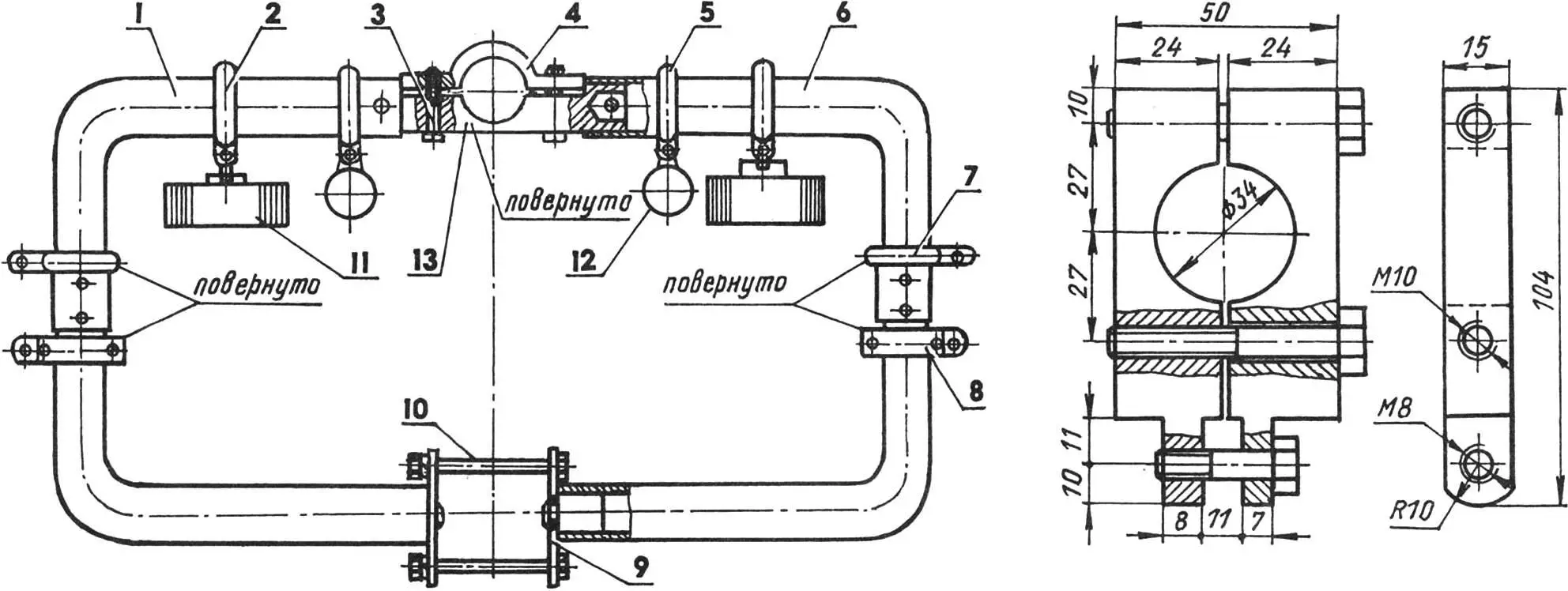
1 — end fitting; 2 — side member
Then from 3 mm thick sheet iron I cut eight plates per wheel for spacers. Their height is 38 mm (half the difference between 18″ and 15″), and the length corresponds to the width of the “Moskvich” disc rim. Before welding, I fitted the plates around the perimeter to the same dimensions in a pack on a milling machine. With an angle grinder with a 3 mm thick cutting disc, I made eight cuts in the “Moskvich” wheel rims (without touching the 15″ mounting diameter), inserted the prepared spacers into them and tack welded them. Having fixed the disc on the axle half-shaft and rotating it, I adjusted the plate positions and welded them finally. I inserted the modified disc into the manufactured 18″ rim and welded the spacers to the cylinder. (As it turned out later, this was done prematurely: the axle design is such that by shifting the discs in the rim cylinder, symmetrical wheel placement relative to the motorcycle’s longitudinal axis can be achieved.)
Then I put the lightened tire with tube on the cylinder and attached the other rim to it with M5 screws (the screw heads inside do not affect the tube). I passed the tube valve through a pre-drilled hole in the cylinder and inflated the tube. The pressure must be such that the tubes seat the tire bead on the motorcycle flanges. A tight fit is guaranteed by identical dimensions, and the tire will not turn on the rim. My wheels have been in operation for more than three years and have not caused any trouble so far, unlike the previous chamber ones, which constantly reminded me of themselves. (If any of the magazine readers supplements this technology, I will be glad.)
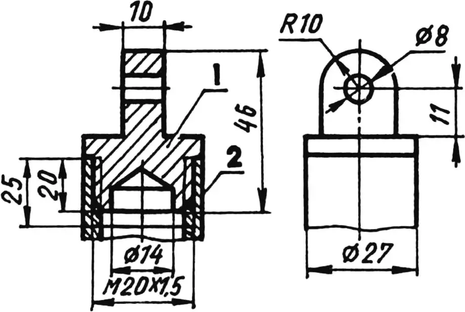
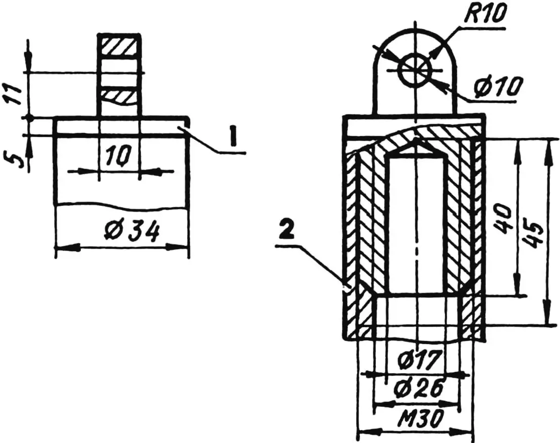
1 — end fitting; 2 — brace
To connect the rear axle to the motorcycle, I made an additional two-side-member frame from inch stainless steel tubes. I bent their rear ends on a tube bender along the contour of the pneumatics. (If there is no possibility or desire to bend the side member tubes, they can be used straight. But then the width of the safety arches will have to be adjusted to the width of the brackets on the rear axle. This option is simpler to manufacture, but the appearance is different.) I connected the front ends of the side members to the safety arches using a special detachable bracket and fixed their position relative to the motorcycle with spacer rods at several more points.
Chrome-plated bed headboards fit perfectly into the pneumatic vehicle design as safety arches. I cut both headboards in half. I attached the upper ends of the halves using a detachable bracket installed on the front tube of the motorcycle frame, and mounted the lower ones on bosses screwed into homemade 8 mm steel engine mounting plates. Before installing the safety arch halves on the frame, I put three clamps on each of them, hung a fog light on one and a horn on another. The third clamp is necessary for connecting the safety arch with a brace tube that connects the motorcycle frame and safety arch at one more point.
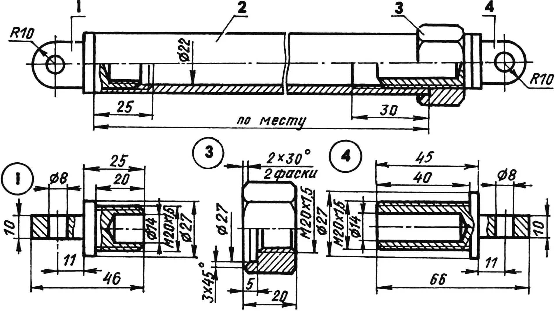
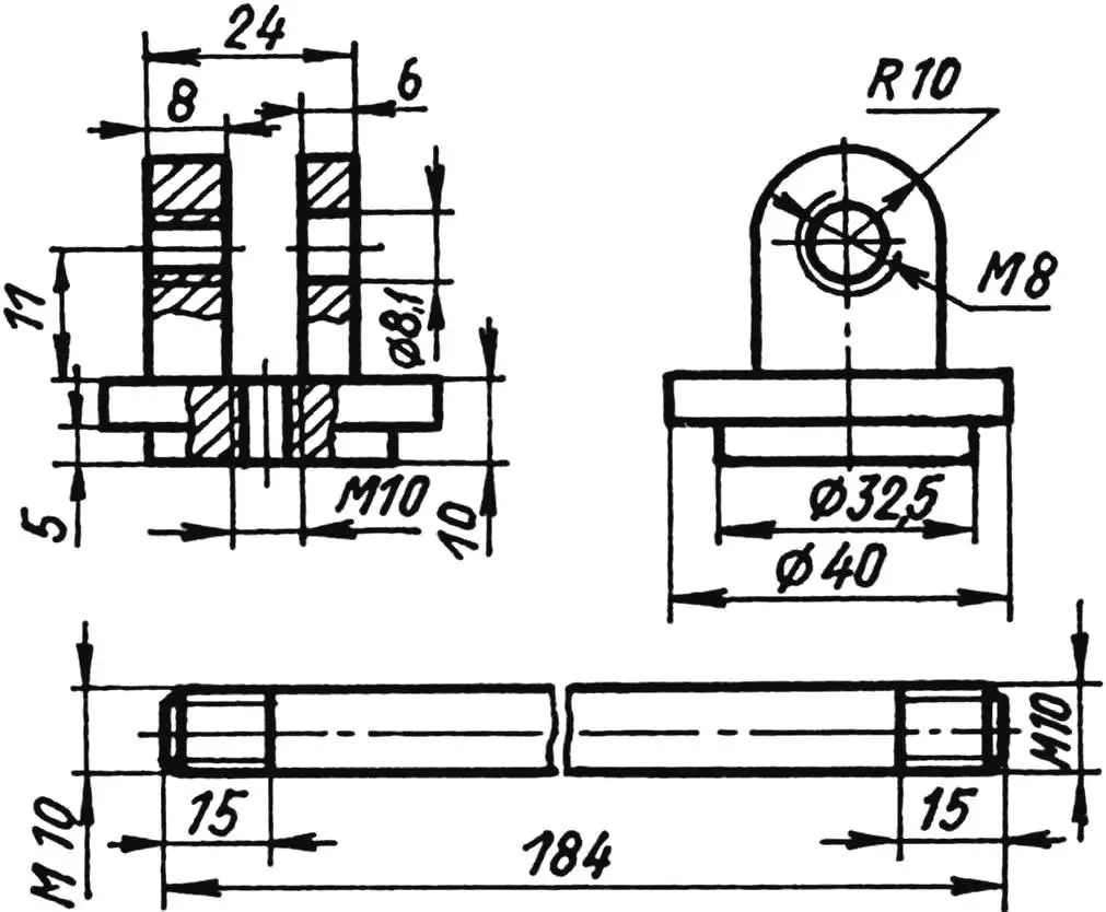
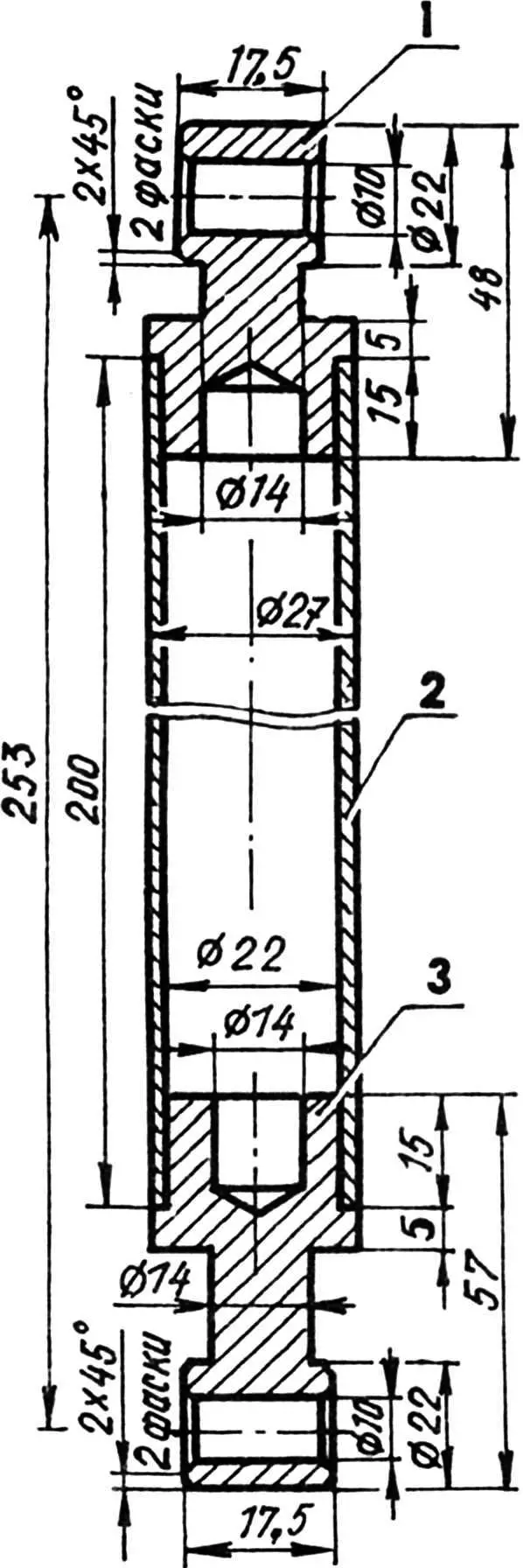
1 — lower end fitting; 2 — rod; 3 — M20x1.5 lock nut (for 24 wrench); 4 — upper end fitting
I secured the safety arches at the top on a bracket installed on the front tube of the motorcycle frame under the fuel tank. To make the bracket, I milled the front clamp from 24 mm thick steel. On a lathe I turned 28.2 mm diameter cylinders on both sides (the inner diameter of the safety arch tube with allowance for interference fit). To lighten the clamp, I made 17 mm diameter blind holes in the cylinders with a drill. In the middle of the clamp I made a semicircular recess with a 20 mm radius, and on its sides — 10 mm diameter holes. The rear clamp is shaped, semicircular with the same inner radius and M10 threaded holes on the “legs”. The clamps wrap around the frame tube and are tightened with two M10 screws. I pressed the safety arch tubes onto the cylinders.
On site, I drilled holes in the tubes and end fittings. I cut M6 threads and secured the parts with two screws. The front face clamp of the bracket and screw heads are chrome-plated.
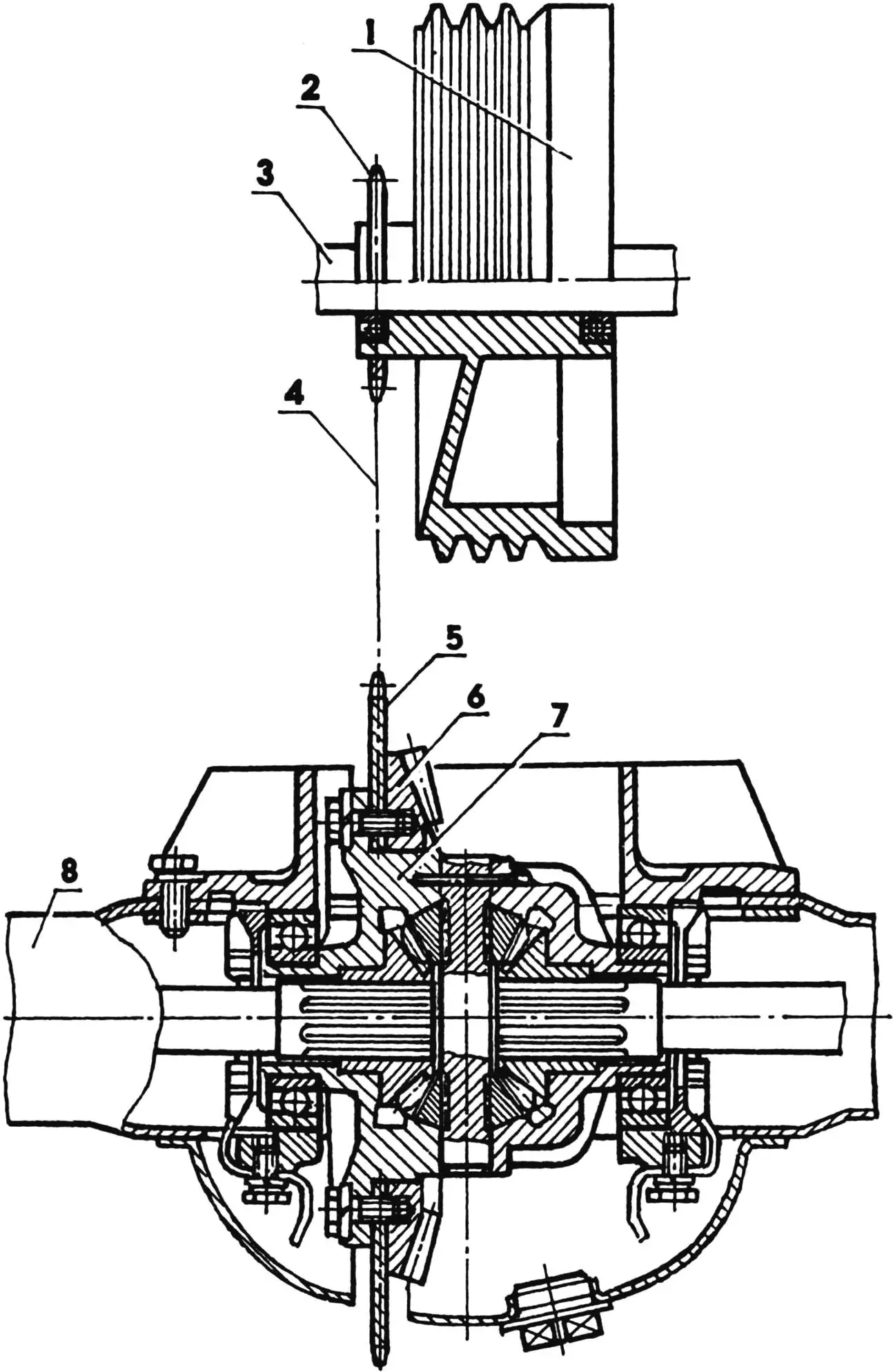
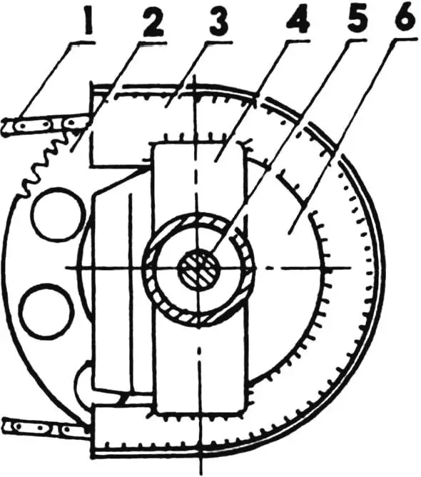
1 — “Izh-56” motorcycle wheel hub; 2 — drive sprocket (z = 18; t = 19.05); 3 — motorcycle rear wheel axle; 4 — drive chain axle; 5 — driven sprocket (z = 56, t = 19.05); 6 — final drive pinion gear; 7 — differential housing; 8 — half-shaft housing
I fixed the arches at the bottom on bosses of the engine mounting cheeks. I cut the cheeks from 8 mm steel. Then I turned bosses whose outer diameter also corresponds to the inner diameter of the tube with allowance for interference fit. I cut M20x1.5 threads both on the turned ends of the bosses and in the drilled holes of the cheeks, screwed the first into the second and pressed the tube onto the boss.
But the mounting of the arches to the motorcycle does not have the reliability and rigidity necessary for mounting the additional frame and tensioning the all-terrain vehicle’s drive chain. Therefore, I additionally connected the arches to the motorcycle frame. For this, I unscrewed the standard bolt for the sidecar mounting rod from under the seat and inserted an axle with two homemade end fittings on the ends in its place. From them to clamps pre-installed on the arches, I ran two braces from 27 mm diameter bed tubes with end fittings. At first I pressed all end fittings into the tubes, but during work it turned out that it’s better to mount them on threads, since later all parts are subject to disassembly for chrome plating.
1,3 — end fittings; 2 — tube
For making rods and struts of the attachment frame, I used 27 mm diameter tubes from the same bed headboards almost everywhere. They are chrome-plated and look good. True, they have holes in the walls, but during assembly I positioned the rods so that these holes were hidden from view.
In the brace tubes I cut M20x1.5 threads to a depth of 25 mm. I also made the rods the same way, only I installed end fittings with M20x1.5 lock nuts for a 24 wrench on them, in which an internal 27 mm diameter recess is made to a depth of 5 mm.
In the end fittings, to lighten them, I drilled 14 mm diameter blind holes. To avoid confusing connecting parts during all-terrain vehicle assembly, I tried to unify them. (If possible, it is desirable to make right-hand threads on one side of the connection and left-hand threads on the other, which will provide better adjustment of the attachment relative to the motorcycle.)
The dimensions of the rods shown in the drawings are recommended, as they will have to be adjusted on site during assembly.
For the all-terrain vehicle I used a “Moskvich-402” rear axle without brake drums. I extracted the main reducer from the housing and cut off the pinion gear “tail” mounting location from the housing with an angle grinder. I annealed the large helical bevel gear in a forge and turned its back side to the mounting diameter and thickness of a sprocket with 56 teeth and 19.05 mm pitch. In the sprocket I drilled corresponding holes and mounted it on the modified gear using standard bolts. I had previously sawed the housing in which the differential is fixed lengthwise with an angle grinder, ensuring free rotation of the sprocket. I kept the differential and half-shafts.
1,4 — rim halves (from “Izh” motorcycle wheel); 2 — M5 screw (9 pcs.); 3 — rim cylinder (steel, sheet s1.5); 5 — disc (wheel from “Moskvich-402” vehicle); 6 — spacer (steel, plate s3, 8 pcs.)
Having marked the sprocket passage location on the axle housing, I also cut it crosswise with an angle grinder. Here I also cut out another 40 mm wide strip so the chain would not catch the housing later.
Then I assembled the axle, centered it and preliminarily welded it with four reinforcing bars to install a protective sprocket housing here. For this, I made two templates from cardboard, one — repeating the outer profile of the axle housing along the cut, the other — along the outer diameter of the sprocket taking into account the chain height and a small clearance. In front of the housing I made protrusions, possibly I will later enclose the chain in rubber tubes. From 2 mm thick steel I cut two parts according to the templates and tack welded them to the axle housing. Along the outer contour I connected both parts with a metal strip.
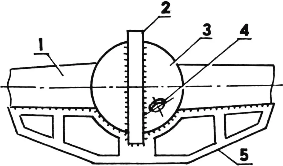
1 — chain (t = 19.05); 2 — driven sprocket; 3 — protective housing (steel, sheet s2); 4 — rear axle beam; 5 — half-shaft; 6 — rear axle housing cap
Before finally welding, I made sure of the coaxiality of the half-shaft housings (“boots”). For greater reliability, I welded another bow truss from 5 mm steel to the bottom of the axle. The axle turned out not too heavy, but quite strong.
To make the hub for the drive sprocket, I took an old “Izh” wheel and, having cut off everything unnecessary on a lathe, left only the brake drum. On the z = 18 sprocket I bored the inner hole to fit the hub tube, mounted one on the other and welded.
1 — half-shaft housing (“boot”); 2 — driven sprocket housing; 3 — axle housing cap; 4 — oil filler hole plug; 5 — bow truss
Since I used a hub from an old model “Izh”, I had to install washers on the axle between it and the rear wheel drive housing, since the spline connection length is shorter and the hub ends up pressed (modern wheel types are better used with a “native” hub; on a lathe “free” it from spoke holes, and weld a sprocket onto the metal bearing housing).
I kept the standard brakes. I would like to warn right away: spun-up wheels of such large diameter have significant inertia, so you cannot brake sharply — large loads are transmitted to the chain, sprockets, differential and half-shafts, which can lead to their failure.
For the same reason, when the shock absorbers compress, the chain sometimes slips. So, instead of shock absorbers I installed two special spacers from the same nickel-plated tubes as the rods. I pressed bushing-end fittings into the tubes.
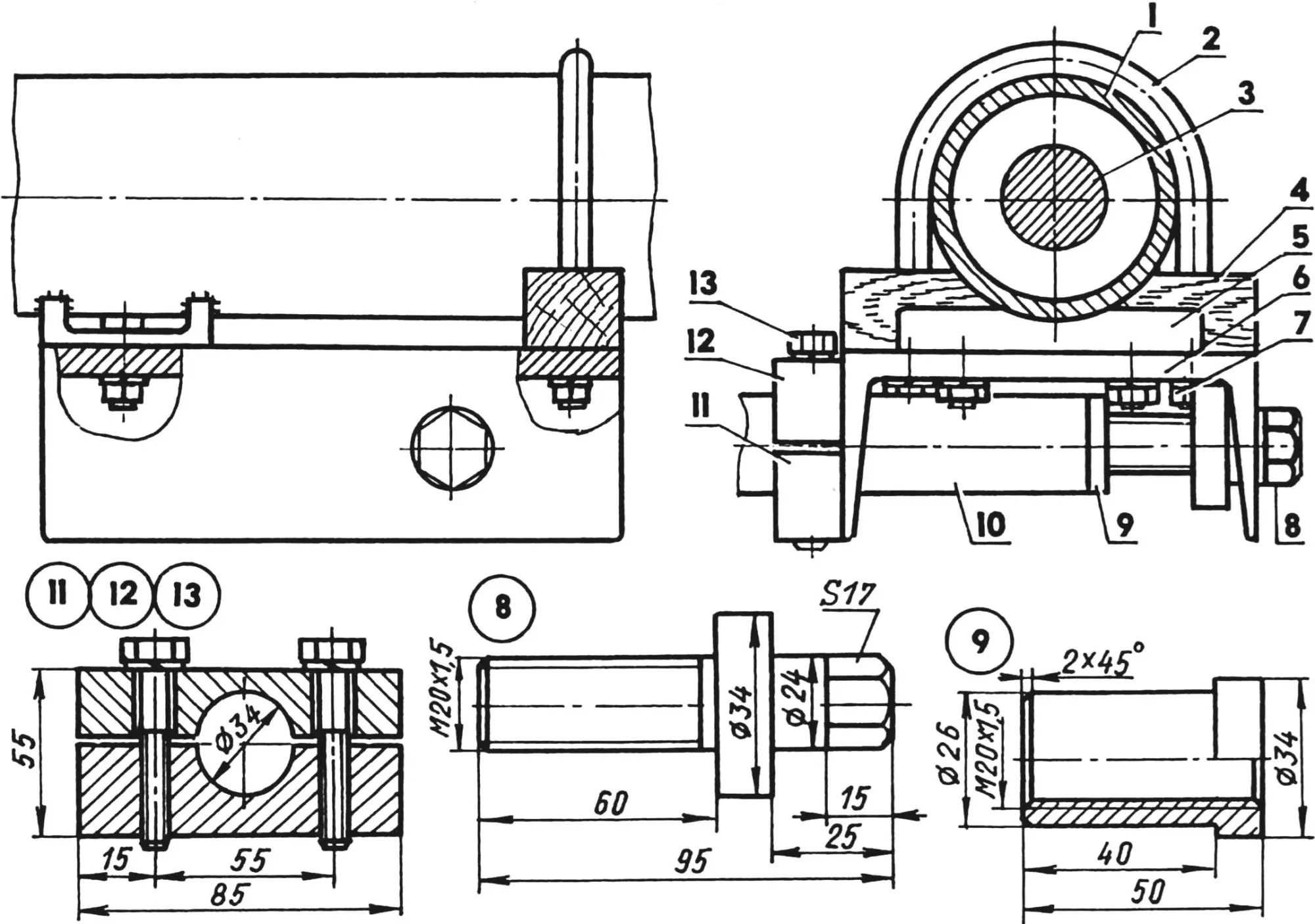
1 — rear axle; 2 — spring shackle (from “Moskvich-402” vehicle spring); 3 — half-shaft; 4 — wooden pad (oak); 5 — axle profiled plate; 6 — unit base (steel, channel No. 12); 7 — M10 nut (4 pcs.); 8 — M20x1.5 tension screw; 9 — M20x1.5 thrust threaded bushing; 10 — additional frame side member; 11 — fixed half of clamp (steel, sheet s20); 12 — movable half of clamp (steel, sheet s20); 13 — M10 screw (2 pcs.)
To connect the rear axle to the motorcycle’s additional frame, I made two docking units. The base of each unit is a No. 12 channel section. On one side I connected it with two M10 bolts to a profiled plate welded to the axle, to which the spring is mounted on the “Moskvich”. On the second side I connected it to the axle housing with “Moskvich” spring shackles thrown over the “boot”.
Between the channel and “boot” I installed a pad of hard wood so the axle axis and channel centerline would be parallel. In the channel flanges I drilled holes: front — for the side member tube diameter, rear — for the tension bolt. When modifying the axle, the sprocket was installed with an offset to the left from the axle center by approximately 30 mm. I took this distance into account when making parts from channels: to maintain wheel symmetry, I made the left part 30 mm longer than the right. I shifted the holes in the left part flanges toward the center by the same distance. The wheel position could be adjusted by shifting the discs in the rims. But I hurried to weld them, and had to do this adjustment with washers on the hubs.
So that in case of drive chain breakage the rear axle would remain on the attachment side member tubes, I made a special detachable bracket with a hole for the tube diameter. I welded the lower half of the bracket with threaded holes to the outside of the channel flange. After chain tensioning, the M10 bolts are tightened, and the bracket compresses the side member tube with its jaws, connecting the motorcycle and attachment as a single structure.
Under the front wheel I installed a quick-release ski (descriptions of its various versions have been repeatedly published in “Modelist-Konstruktor”). Deep soft snow is, naturally, an obstacle for my pneumatic vehicle — the mass of the motorcycle itself makes itself felt. Its element is dense snow crust and off-road terrain.
V. BARANOV
Recommend to read
 GARDEN HOUSE-SHUT
A garden house designed according to the “hut” scheme differs from traditional buildings in that it does not have walls: they are replaced by an enlarged roof, under which all the living...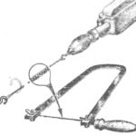 IF THERE ARE NO FILES
Will not save enough for beginners of lobzikovye saws — everybody knows the head of the technical group. We found a simple way out of this situation and would like to share an idea with...
