My first pendulum saw was made from drawings proposed by V. Zaitsev in the magazine “Modelist-Konstruktor” No. 12 for 1985. Indeed, for working with metal using a cutting wheel this tool is simply indispensable, but for working with wood the saw must also be given longitudinal motion. Therefore I had to make another version.
The design of the second pendulum saw, compared with the first, has the following additional capabilities:
– longitudinal travel is provided;
– the electric motor is mounted on a bracket and can move along the frame to tension the belt and not depend on a single belt length size;
– the saw can be rotated around the axis and set at an angle from 0° to 45°, which is sometimes necessary when making certain types of dovetails in carpentry products;
– the saw can be locked against oscillation in any position;
– there is a stop that allows setting the cutting depth.
Figure 1 shows the general view of the pendulum saw without the protective covers for the belt and the disc saw.
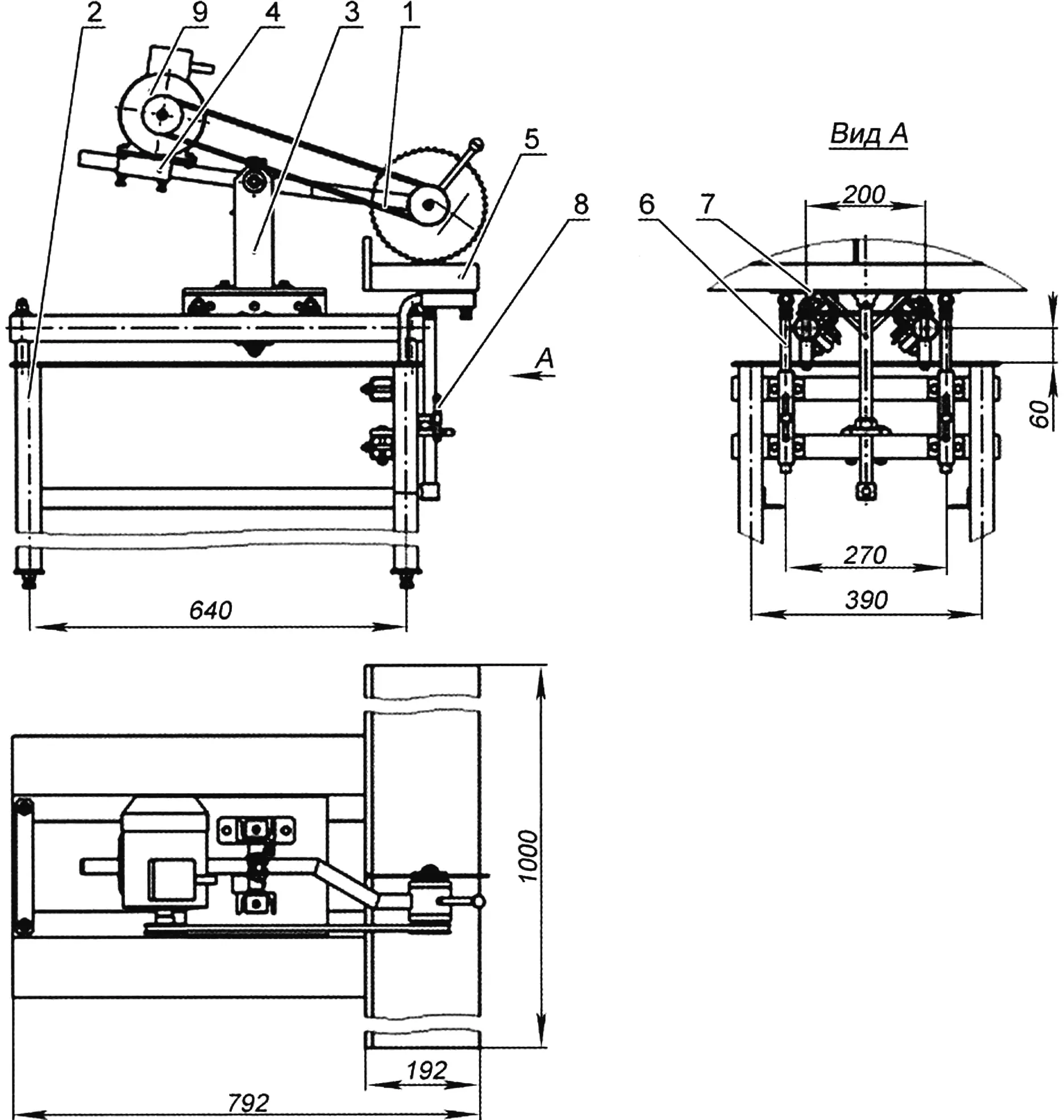
1 – frame; 2 – table; 3 – carriage; 4 – bracket; 5 – lifting table; 6 – slide; 7 – lifting screw; 8 – locking screw; 9 – electric motor N=0.4 kW, n=1500 rpm
The machine consists of the following main units:
The frame (item 1) is installed in the carriage bushing and, after balancing, is secured (balancing should be done with the electric motor and protective covers installed).
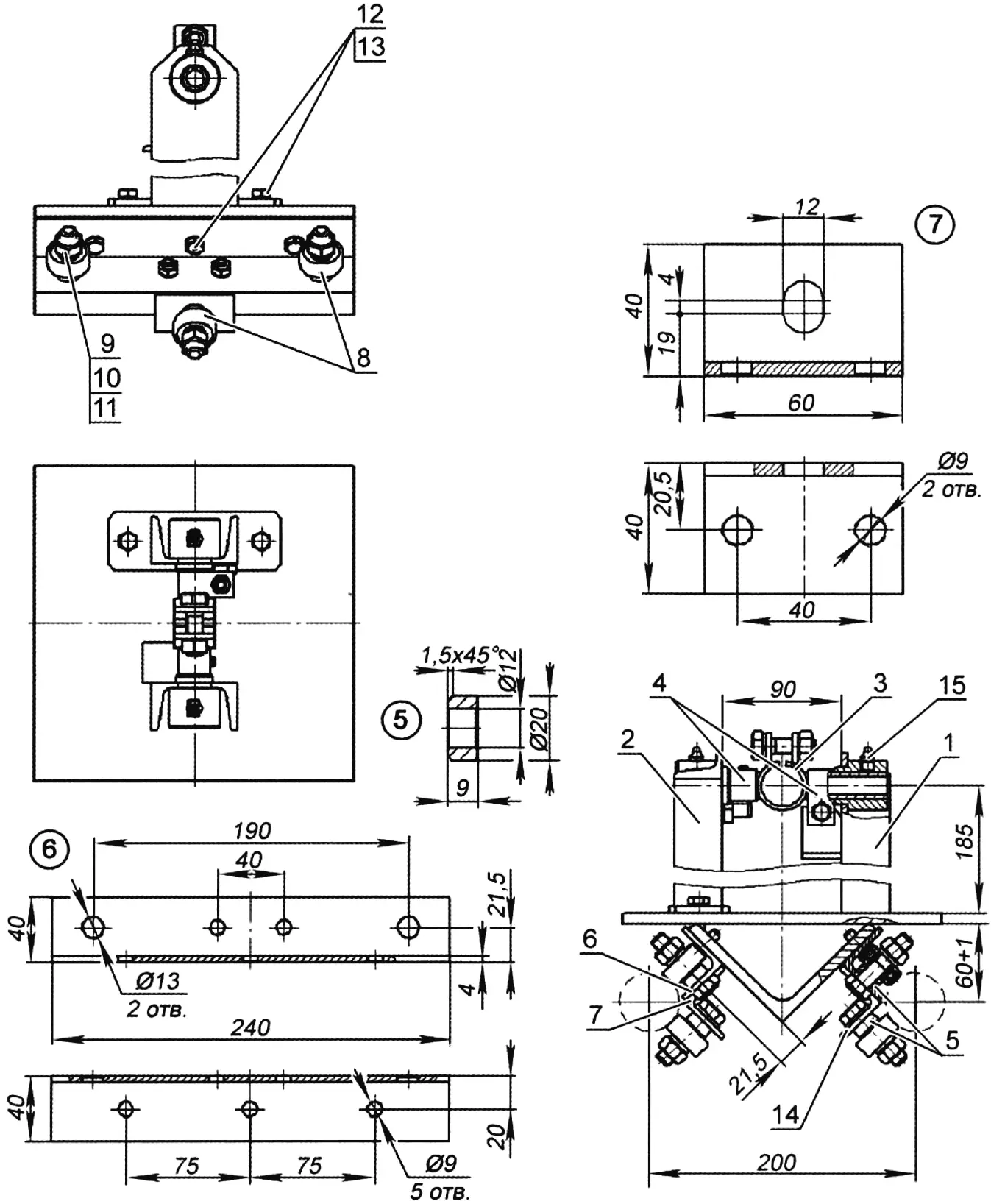
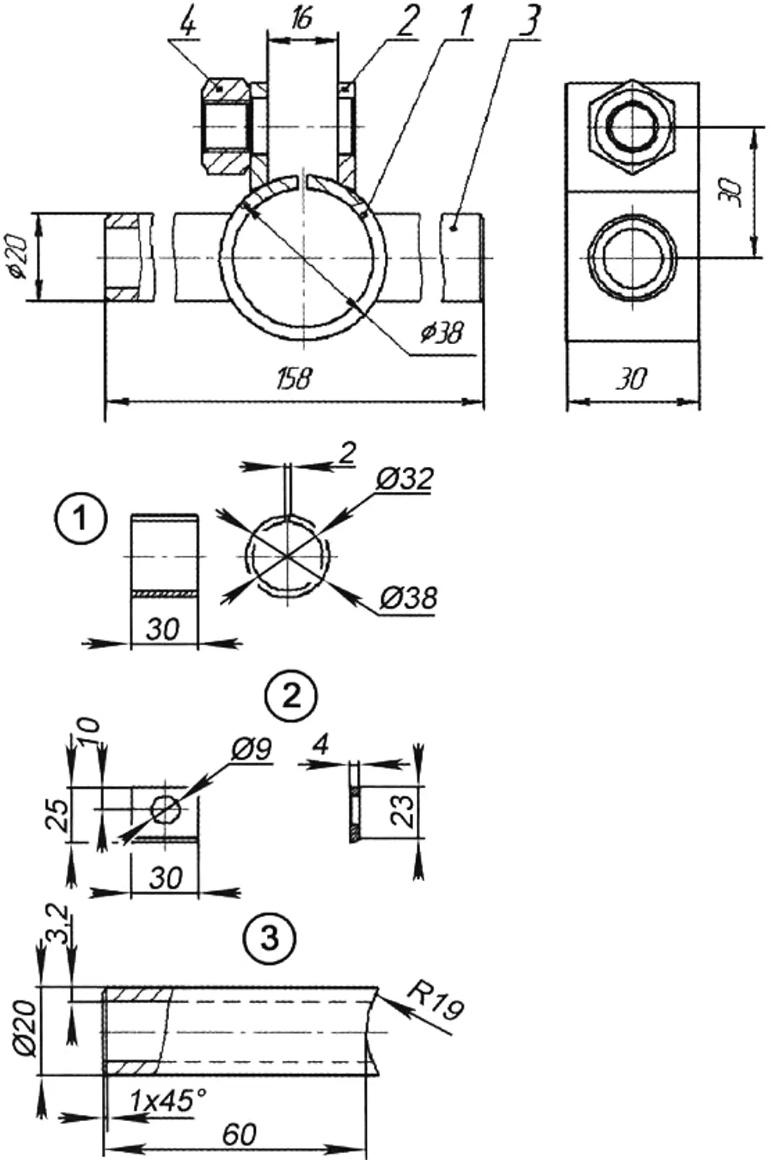
1 – body; 2 – upright; 3 – axle; 4 – clamp (2 pcs.); 5 – bushing (6 pcs.); 6 – angle; 8 – bearing 180501; 9 – bolt M12x50; 10 – nut M12; 11 – washer 12.65G; 12 – bolt M8x20; 13 – washer 8.65G; 14 – washer 12; 15 – grease fitting
– The table (item 2) is a 5 mm thick sheet measuring 700×450 mm, mounted on legs made of square tubing 40x40x2.5 mm, stiffened in the longitudinal and transverse directions with equal-leg angles 35×4 mm.
– The carriage (item 3, fig. 2).
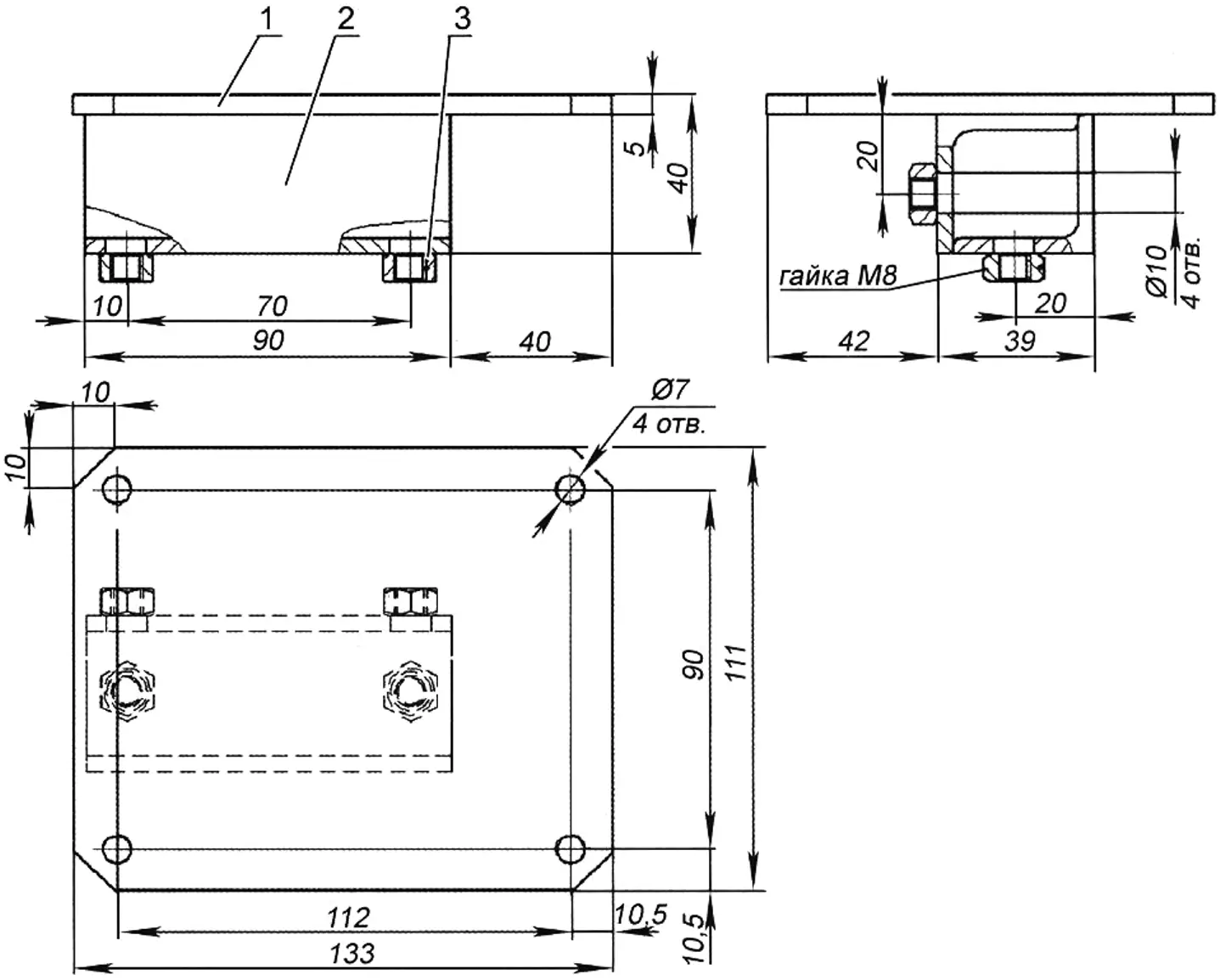
– The bracket for mounting the electric motor (item 4, fig. 5) is installed on the frame and secured with four bolts.
– The lifting table (item 5).
– The slide (item 6, 2 pcs.).
– The lifting screw M20 (item 7).
– The locking screws (item 8, 2 pcs.).
– The electric motor (item 9).
Drawings of the table, the saw bearing unit, and the lifting table have been published in the magazine more than once, so I think there is no need to repeat them.
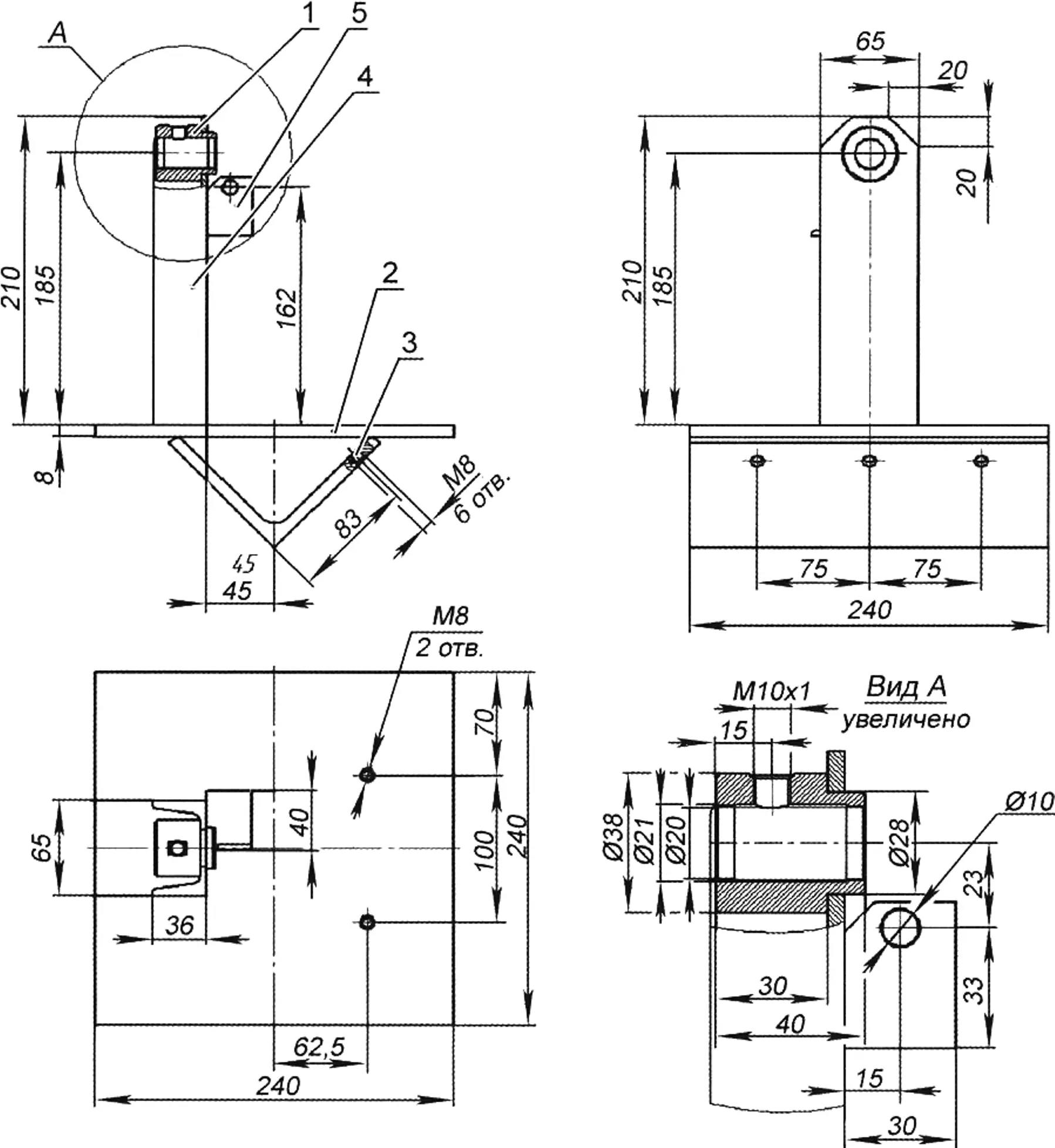
1 – bushing; 2 – base (steel sheet 240×240, s5); 3 – angle 100x100x8; 4 – upright (channel No. 6.5); 5 – stop (angle 40x40x4)
Figure 2 shows the assembled carriage, consisting of: the body (item 1), the upright (item 2), the axle (item 3), the clamps (item 4, 2 pcs.), the bushings (item 5, 6 pcs.), the angles (items 6 and 7, 2 pcs. each), bearings N180501 GOST 8882-75 or N80203 GOST 7242-81 (item 8, 6 pcs.).
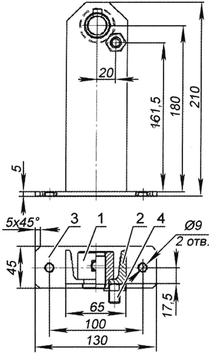
1 – bushing; 2 – upright (channel No. 6.5); 3 – plate; 4 – bolt M12x14
The carriage body (fig. 3) is welded. It consists of the base (item 2) measuring 240×240 mm, made of 5 mm steel sheet; the upright (item 4, channel No. 6.5 L=210 mm); the support angle (item 3); the bushing (item 1); and the angle (item 4) intended for fastening the clamp that locks the saw frame.
1 – bushing; 2 – pad; 3 – axle; 4 – nut M8
The parts of the carriage body and upright (fig. 4), as well as on drawings of some other units, are not shown, since all dimensions are given on the “assemblies.”
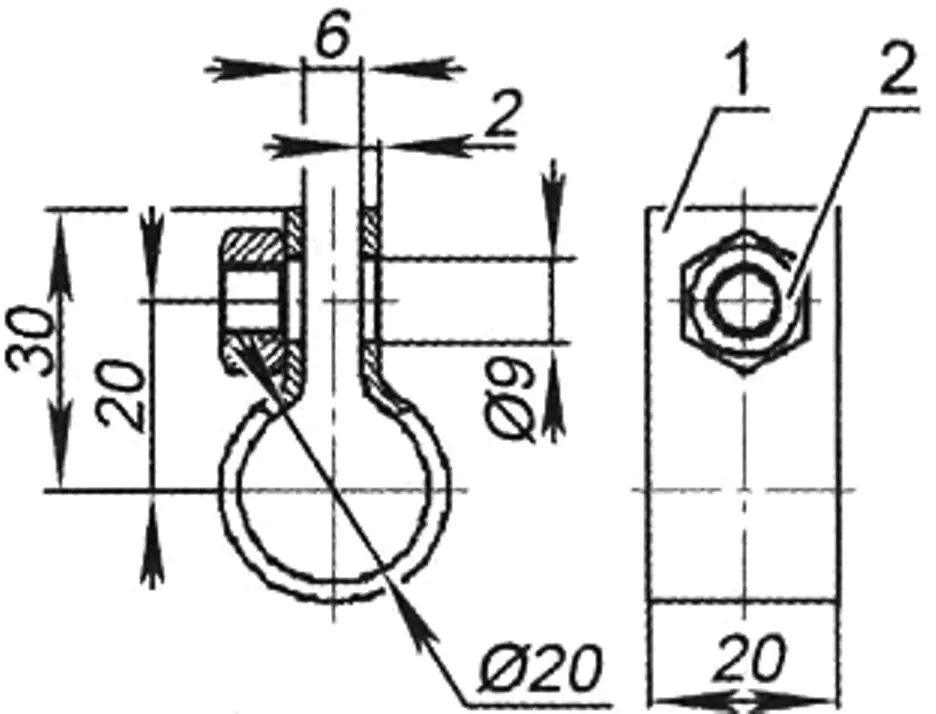
1 – clamp; 2 – nut M8
Bolt M12x14 (fig. 4, item 4) serves as a limiter for the cutting depth.
1 – plate; 2 – angle 35x35x4; 3 – nut M8
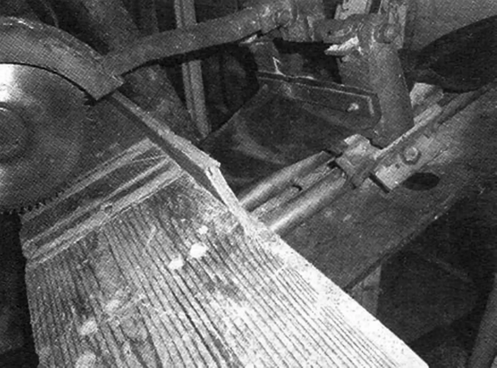
The cover photograph shows rubber protective shields that prevent sawdust from getting onto the machine guides.
“Modelist-Konstruktor” No. 6’2016, A. CHMYR, Izium, Kharkiv region, Ukraine
Recommend to read
 PATTERNS — ROLLER
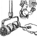
When painting with a roller you get a good smooth surface, often even better quality than that made with a brush. However, if you need the same brush to hold the winding "tracks" with...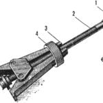 CORKSCREW FOR BEARING
How diverse is pressed in units of parts so numerous and adaptations for wheel — pullers. However, the majority of them operates on the principle of ejection. Well, if the part is...
